Abstract
Electrical clearance conflicts may be identified during NERC or other reliability review programs of existing infrastructure due to the creep of the conductor over a long period, vegetation growth, encroachment, or other right-of-way (ROW) related scenarios. Utility engineers are often presented with challenges to resolve such conflicts on existing transmission lines as most solutions require expensive infrastructure upgrades. In such instances, it would be beneficial to explore out-of-the-box solutions to improve electrical clearance. This paper will review the feasibility of various methods such as the use of suspended dead-end or floating dead-end assemblies for suspension structures, the use of insulated cross- arms on towers, modifications to lattice tower cage to raise the cross-arms, nip-tuck fixes to bottom phase conductors, use of high-temperature-low-sag conductors as a system-wide solution to address clearance concerns.
Background
In the realm of electrical power systems, ensuring safety and reliability is paramount. One critical aspect that directly influences the integrity of these systems is the determination and adherence to proper electrical clearances. Electrical clearances define the minimum distances required to be maintained between conductive elements, such as power lines, equipment, and structures, to prevent hazardous conditions and mitigate the risks associated with electrical faults and failures.
Maintaining adequate electrical clearances is essential to ensure the safe and reliable operation of power systems. Adhering to established clearance standards mitigates the risks associated with electrical faults, reduces the likelihood of accidents, and enhances the overall integrity of power infrastructure. In this technical paper, we explore different methods and strategies to improve electrical clearances in accordance with the latest guidelines provided by the National Electrical Safety Code (NESC) 2023 and the North American Electric Reliability Corporation (NERC).
This technical paper aims to examine various methods and strategies to enhance electrical clearances in alignment with the NESC 2023 and NERC standards. We will explore both traditional approaches and innovative technologies that can be employed to improve clearance distances, minimize risks, and optimize the overall performance of power systems. By embracing the methods outlined in this paper, power delivery service stakeholders can not only improve safety and reliability but also realize operational efficiencies and optimize their investments.
This paper utilizes a problem statement of a double circuit 230kV transmission line supported over lattice towers crossing over an elevated highway. The solutions discussed in this paper are adopted and the improved clearances are calculated in each case. By presenting a summary of the calculated clearances, the paper offers valuable insights into the extent of clearance enhancements achieved through the methods discussed.
In the subsequent sections of this paper, we will delve deeper into the various methods and strategies, discussing their benefits, implementation considerations, and potential impact on the safety and reliability of power systems. Through this exploration, we hope to contribute to the ongoing efforts to improve electrical clearances and ensure the continued integrity of power infrastructure in an ever-evolving technological landscape.
Solutions to Mitigate Electrical Clearance Conflicts
Generally, the geometrical dimensions of a transmission/distribution structure like the height of the structure and length of crossarms are governed by its clearance requirements. For a new design, the structure geometry can be designed to meet the electrical clearance requirements. However, for an existing transmission line, there are more challenges to consider. Existing transmission lines have conflicts because of the after-creep and after-load effects on the wire. Below are some of the conventional solutions.
-
Replacing the existing structure with a newly designed structure with increased height
-
Replacing/re-tensioning the conductors
-
Adding intermediate structures
-
Derating the transmission/distribution circuit temperature
These solutions, which may seem to be the simplest solutions, are often very expensive to execute.
The replacement of the existing structure with a new structure or adding an intermediate structure may have issues with the new set location. There can be several reasons like the presence of a driveway or underground utilities. The replacement or re-tensioning of existing conductors with new conductors may cause problems to structures if they are not designed for these increased changes in loads. Re-tensioning or replacement of the conductors may not be possible on derated or damaged structures.
In this paper, we have enlisted some methods to overcome these challenges in an economical and innovative way.
In this paper, we have largely limited the discussion to electrical clearance solutions that follows an unorthodox approach, and which can be used as an economical and better design solution. The implementation of these solutions can allow utilities to maintain compliance without costly structure or line replacements and rebuilds. For every option that has been considered, a comprehensive analysis is provided regarding the approach's implementation, including an in-depth exploration of its advantages and potential drawbacks. As a majority of these alternatives involve non-traditional materials, hardware components, and assemblies, we have refrained from delving into the economic considerations associated with each option. These factors might differ based on individual vendors and manufacturers.
Following solutions are discussed in the paper,
-
Suspended Dead-end or Floating Dead-end
-
Insulated Crossarms on Structures
-
Structure Raise Modifications
-
Nip-tuck Fixes
-
Use of High-Temperature-Low-Sag (HLTS) Conductors
-
Suspended Dead-end or Floating Dead-end
Numerous utility companies are striving to enhance their systems, all while keeping a keen eye on cost- effectiveness. In certain cases, the need for a complete structure or conductor upgrade might not be warranted; the issue might be as minor as a clearance violation in a limited number of spans. Replacing
entire structures would prove economically inefficient in such scenarios. As a remedy, the concept of utilizing floating dead-ends is generally explored to address localized clearance problems within a span.
Floating dead-ends come into play when addressing localized clearance issues in a span. Their purpose is to reduce the suspension insulator string's length on a tangent structure, thereby elevating the point of conductor attachment. This reduction in insulator length effectively enhances clearance levels but necessitates the addition of two strain insulators on opposite sides of the structure. In other words, these strain insulators are anchored to the end of the shortened suspension insulator, forming a jumper loop that traverses through the suspension configuration. Employing a shorter suspension insulator ensures that the structure continues to function as a tangent. Any imbalanced tensions caused by conductor movement are evenly distributed across the remaining length of the insulator string. The specific length of the insulator string varies and is based on its strength rating.
This heightened clearance potential could serve as a solution for multiple existing lines where simple enhancements are required. However, it's important to acknowledge that floating dead-ends also have their drawbacks. Despite the improved clearances, certain structural elements might demand alteration as well. This could entail resizing angle members, along with introducing redundant or brace members on towers.
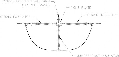
Figure 1 - Floating or Suspension Dead-end Assembly Standard Components
Benefits of this solution:
-
The necessary material hardware for implementing this choice is standardized and readily available, eliminating the need for specialized engineering or collaboration with niche vendors.
-
The alteration in load distribution on existing structures is insignificant. Consequently, this option can be integrated with only minor adjustments to the current structures.
-
The installation process is simple and can be executed within relatively brief outages.
Engineers must assess the electrical clearances of the floating dead-end jumper loop to the structure, as well as phase-to-phase clearances. Due to these clearance limitations, this solution may not be suitable for certain structural configurations. Additionally, the applicability of floating dead-end assemblies pertains specifically to suspension structures. In cases where clearance conflicts arise in spans with angle or dead- end structures, this approach is not viable.
-
-
Insulated Crossarms on Structures
An innovative approach for achieving additional clearance involves the use of insulated crossarms, which replace the steel crossarm and suspension insulator strings found on traditional lattice towers and steel poles. This allows the conductors to be directly attached to the structure's crossarm. The main purpose of an insulated crossarm is to serve as a substitute for the conventional crossarm or davit arm. This integrated assembly fulfills both the mechanical support function and provides electrical insulation for the attached conductor.
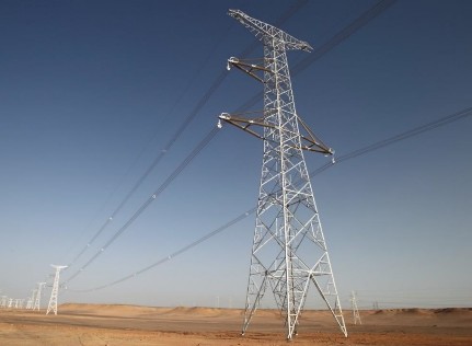
Typically, post insulators are used as crossarms which possess excellent compressive strength. To these posts, installing an insulated crossarm does not necessitate any modifications to the existing tower or tower design. With modern mounting arrangements, insulated crossarms can be fitted onto any standard structure design. The key advantage of utilizing such crossarms is that the swing of the insulator under wind blowout conditions is minimized to a minimum.
Figure 2 - Composite Insulated Cross-Arm (CICA) [1], Integrated Solution for Compact Lines
This limitation is determined by the swinging of the suspension clamp instead of the entire length of the insulator string. Furthermore, there is no need to increase the tower's height to accommodate the length of the insulator string itself.
Various utilities nationwide have implemented the use of braced post assemblies on transmission structures to enhance electrical clearances in transmission lines and minimize insulator swing during blowout scenarios. Typically, these braced post assemblies consist of a rigid cantilever post insulator connected to the structure through a suspension insulator, offering improved vertical and transverse load-bearing capabilities compared to traditional line post assemblies. Nonetheless, it is essential to recognize that the primary drawback of this assembly is its limited capacity to withstand out-of-plane (longitudinal) loads, which could lead to post insulator failure if longitudinal balance is compromised.
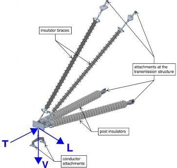
Loads that act on an insulated crossarm, are (a) Vertical Loads [V] from conductor and ice (if applicable),
(b) Transverse Loads [T] from wind and line angle (if applicable) and (c) Longitudinal Loads [L] from unequal conductor tensions in ahead and back spans or from a broken conductor on one side (Broken Wire condition). Vertical loads are mainly taken by the insulator brace whereas the transverse loads are taken by the post insulator, which is loaded in buckling when these loads are compressive in nature. The longitudinal load needs to be taken into consideration in the dimensioning of the insulated crossarm.
Figure 3 - 3D Rendering Insulated Crossarm [1]
If the longitudinal load requirement is too high for the post insulator diameters available, vendors can create specialized insulated crossarm assemblies having multiple post insulators, as shown in the rendering above.
Benefits of this solution:
-
The use of insulated crossarms on transmission structures will help reduce Right-of-Way (ROW) widths and thereby save utilities costs for ROW and acquisition.
-
Due to the configuration of the insulated crossarms, the use of I and V-string assemblies is eliminated and hence, greater vertical clearances are made available.
-
For lattice tower structures, insulated crossarms replace the conventional crossarms and hence, lesser steel is required thereby helping shorten tower assembly time.
-
Because of the presence of multiple insulators in the insulated crossarm assembly, there is a fail- safe redundancy that will prevent a total collapse of a transmission line in the event there is a failure in the insulator.
The only limitation one may need to consider when using insulated crossarms on transmission structures is to account for the increased hardware assembly cost per structure. However, the use of insulated crossarms will help utilities save in ROW, material and construction costs which would likely result in overall reduced project costs.
-
-
Structure Raise Modifications
Conventional methods of enhancing electrical clearances involve replacing transmission structures with taller ones or adding intermediate structures. However, these approaches often force utilities to make difficult decisions, replacing relatively new structures due to clearance conflicts or increased clearance requirements. Such solutions not only escalate project costs but also necessitate outages for installation.
In contrast, the innovative solutions discussed in sections 3.1 and 3.2 offer a way to improve electrical clearances while retaining existing structures. Nonetheless, their effectiveness is limited by the conductor attachment's position concerning the insulator attachment on tangent/suspension structures.
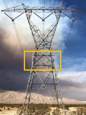
In this section, we will explore modifications that physically elevate the height of existing structures. Expert industry consultants are available to design such modifications based on the required height increase and the existing structure's capacity. By utilizing hydraulic lifts, a section of the structure can be raised to the desired height, and the modification can be seamlessly integrated. A noteworthy advantage is that this type of modification can be executed on an energized line without necessitating an outage, providing considerable benefits to utilities.
-
Modifications to Lattice Towers
During the installation of a structure-raise modification on lattice towers, a specially designed new section of tower members is introduced, fitting in-between the existing sections. The positioning of this modification varies depending on the tower's geometry and the required height increase. It can be implemented either within the tower cage, just above the waist of the tower, or within the tower body itself. The new section can be customized to have different heights to suit specific needs. However, due to engineering constraints, the height adjustments for lattice towers are typically limited within the range of 5ft to 20ft. The minimum height for the new section panel, along with its bracing and strut members, is set at 5ft, while the upper limit is generally restricted to 20ft.
Figure 4 - 10ft Mid-body Ext for 500kV Tower [5]
Engineering considerations for the structure-raise modification are as follows:
-
All members of the new section are sized to withstand the design load cases of the original tower.
-
The increase in overall height will result in higher wind loads on the towers, necessitating careful consideration for extreme wind load cases.
-
Existing tower members must undergo load checks for the increased loads. If overstress is observed during analysis, modifications may be required for these existing members. Both existing and new members can be checked for these installation loads, as deemed appropriate by the engineer on record.
-
The existing foundations of the tower should be checked for increased loads. If the loads exceed the design base reactions, foundation augmentation might be necessary.
-
The design of new section members ensures that the connection hole patterns match those of the existing members above and below. Special measures shall be taken to avoid the need for drilling additional holes in existing tower members, as this could compromise their capacity.
-
It is essential to check adjacent structures for uplift and other changes in loading due to the heightened structure of the raised tower. This assessment may limit the extent to which a tower can be raised.
Construction considerations for the structure-raise modification are as follows:
-
A specialized hydraulic lifting system will be utilized, anchored to the existing tower, meeting fall protection regulations (OSHA 1910.269, ANSI C2, etc.) [3].
-
When lifting the tower section to incorporate the new modification, connecting bolts will be removed one-by-one. The lifting system will facilitate load transfer between the upper and lower portions of the tower. The vendor will verify the vertical, transverse, and longitudinal load ratings of this lifting system.
-
During the installation of the modified section, some existing tower members may experience flexural loading due to the weight of construction workers climbing or working on them. These climbing loads will be checked for the relevant members, considering an independent vertical load of 250 lb with a load factor of 1.5, following ASCE 74-2020, Section 3.3 [4].
-
Construction operations will be conducted under calm weather conditions, considering the lowest ambient temperature anticipated during installation with a 3 psf wind, per ASCE 74-2020.
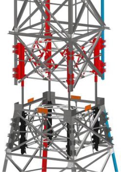
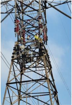
Figure 5 - Lattice Tower raises using a specialized Lift System [5]
-
-
Modifications to Poles (wood)
Similar to the lattice tower modifications that raise the height of the structure to mitigate electrical clearance conflicts, modifications can be engineered for wood pole structures. These types of modifications can be designed for raising the height of wood pole structures from 5ft to 20ft. In concept, the wood pole structure is cut at a specified height above ground level, external attachment in the form of a steel bracket is secured at the cut line, the portion of the wood pole structure above the cut is then lifted using a hydraulic lifting system. The sequence of construction operations to install these modifications is such that an external support is provided to the structure and appropriate load flow from the top to the bottom of the structure through the modification parts is observed.
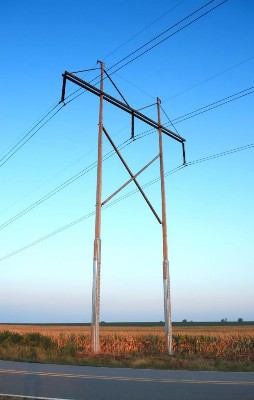
Some considerations for this type of modification are as follows:
-
These modifications are generally engineered for tangent and small angle suspension structures. For angled and dead- end structures, it may be challenging to perform this modification with full loads acting on the structure.
-
Typically, wood pole structures are designed to have direct embedded foundations with embedment depth set to 10% of pole height plus 2ft, widely considered as the industry thumb rule. With the pole height raised by this modification, the foundation will need to be checked. For example, if the pole is being raised by 20ft, and the original structure is designed to have 10% original height plus 2ft foundation embedment depth, then the new structure’s foundation embedment depth will be short by at least 2ft if the industry thumb rule was to be followed.
-
Before starting the lifting procedure, the ground wire on the pole may need to be cut. The utility will need to ensure the proper grounding method is in place, consistent with their standards, by installing a floating ground jumper.
Figure 6 - 15ft raise for 345kV H-Frame using specialized modification [6]
Benefits of this solution:
-
With minimal modifications to the existing structures, additional clearance of 5-20 ft can be achieved.
-
These modifications can be designed to be installed without the need for an outage.
-
Since such systems are modular, these modifications can be installed in locations with difficult access, heli-lifted to the site, which isn’t generally the case with conventional construction equipment.
Since this solution involves installing structure-specific custom modifications based on the structure type and clearance improvement margin required, this solution cannot be readily implemented. The duration of
engineering time to design such modifications also largely depends on the geometric complexity of the existing structures. Furthermore, to install such modifications, trained and qualified labor may be needed.
-
-
-
-
Nip-tuck Fixes
The 'Nip-Tuck Method' is an effective approach to achieve additional clearance, although it is still considered unconventional despite its adoption by utilities across the US for a considerable time.
The fundamental principle involves removing a portion of the wire to reduce its length and subsequently lower the sag, creating a 'nip' in the span. By removing a specified portion of the wire from the span facing clearance issues, the sag is reduced. The wires are then spliced together to establish an effective connection. However, it is essential to consider that removing a portion of the wire from the span will increase tension. This approach can induce some longitudinal imbalance on the structure, leading to insulator swing, especially when implemented on spans between tangent or suspension structures. Most utilities prefer to maintain the alignment of all suspension insulators and clamps as plumb.
To address such scenarios, the 'Tuck operation' can be adopted, wherein the wire is slipped (Tuck) at the tangent supports instead. Additionally, the wire length can be slipped into the jumper loop of a dead-end structure if it is feasible and proximate to the span facing clearance conflicts. This technique allows for achieving the desired clearance improvement while minimizing the potential for insulator swing issues. An important caveat to the tuck operation is that the clearance in the adjacent span where the wire is slipped to reduces and hence, this is can only be performed when the spans adjacent to the span in question facing clearance conflicts have sufficient clearance margins.
In practice, nip and tuck operations are often performed in tandem to achieve the desired clearance improvement while also ensuring the suspension insulators or the suspension clamps remain plumb.
Engineers follow the 'Nip and Tuck' approach to address electrical clearance conflicts by implementing the following steps:
-
Calculate the clearance margin to determine the required mitigation level.
-
Utilize finite element modeling tools like PLS-CADD with the SAPS module to adjust the amount of conductor to be removed from the conflicting span by editing span-specific wire lengths.
-
The angle of insulator swing indicates the amount and direction in which the conductor needs to be tucked to re-align the insulator. [7]
-
Conduct iterative Nip and Tuck operations in PLS-CADD until the desired clearance margin is achieved.
-
Verify the effect of resulting unbalanced load on the existing structures to ensure their structural integrity.
Benefits of this solution:
-
The potential to gain additional clearance, up to a few feet (typically less than 5ft), through adjustments to existing wire lengths.
-
No need for modifications for existing structures if their structural integrity is confirmed.
-
Shorter outage periods because the Nip and Tuck fixes can be executed relatively quickly.
-
No requirement for additional training, licensing, or qualifications for the transmission & distribution operations construction crew carrying out these fixes.
However, a major limitation is the introduction of an unbalanced longitudinal load, which necessitates checking the existing structures. This solution may not always be feasible for tangent structures with limited longitudinal capacity.
-
-
Use of High-Temperature-Low-Sag (HTLS) Conductors
For several decades, the utilities industry has aimed to find alternatives to conventional conductors. Several factors including population and natural disasters are driving the need for hardening of circuits and associated infrastructure around the country. As of late, Aluminum Conductor Steel Supported (ACSS) cables have been a common choice for upgrades. Round wire 1350 aluminum that contains annealed and intermediate tempers for electrical purposes allows for elevated temperatures up to 482 °F (250 °C) without loss of strength. There are one or more layers of hard drawn annealed aluminum along with one composite concentric stranded layer. With ACSS, the steel core carries most or all the mechanical load [6].
Though ACSS conductors have a higher maximum operating temperature with less strength loss than ACSR conductors, they unfortunately aren’t always the best choice for projects involving long spans that cross rivers or highways. To span these types of crossings, utilities have begun using high-temperature low-sag (HTLS) conductors with composite type cores. These types of cables consist of Aluminum Conductor Composite Reinforced (ACCR), Aluminum Conductor Composite Core (ACCC), and Aluminum Conductor Composite Supported (ACCS) also known as C7 [8] [9]. The tables below compare the properties of four different conductors. The first being an ACSS conductor and the other three being HTLS conductors described above.
Conductor Type
MOT F (C)
Ampacity
RBS (lbs)
Overall Diameter (in)
Total Area (in2)
Unit Weight (lbs/ft)
959.6 ACSS "Suwannee"
392 (200)
1828
33100
1.108
0.8762
1.317
995 ACCS C7 "T13"
356 (180)
1748
33500
1.108
0.8847
1.001
1033 ACCR "Curlew"
410 (210)
1939
35600
1.247
0.917
1.134
1581.6 ACCC "Bittern"
356 (180)
2229
45200
1.345
1.335
1.563
Table 1 - Conductor Properties Comparison
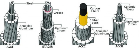
Figure 7 - Cross Section of Various Conductor Types [10]
Benefits of this solution:
-
HTLS conductors have several benefits over conventional conductors such as flexibility, thermal stability, corrosion resistance and low coefficient of thermal expansion. Thus, the conductors can be tensioned following similar tension limits as other conventional conductors and will have lesser sag values at their maximum operating temperatures.
-
Furthermore, the main advantage is that HTLS conductors can enhance security reserves and transmission capacity without impacting the negotiated right-of-way, ideally with minor modifications of towers (mostly clamps of the conductors and their mountings or light tower’s reinforcement) and sometimes fewer towers.
-
Reconductoring with HTLS conductors can be a step towards improving the reliability of the system by installing conductors with higher ampacities and minimal changes to existing structures.
-
HTLS conductors can be installed on long spans, work at higher temperatures without significant loss of strength, are preferred in corrosive and coastal environments due to their excellent resistance to corrosion and are easy to install.
-
Furthermore, the main advantage is that HTLS conductors can enhance security reserves and transmission capacity without impacting the negotiated right-of-way, ideally with minor modifications of towers (mostly clamps of the conductors and their mountings or light tower’s reinforcement) and sometimes fewer towers.
Implementing HTLS conductors to address electrical clearance issues necessitates extended line outages due to their utilization in a full or partial line reconductoring. Utility engineers must take into account the lead times associated with procuring HTLS conductors. It's worth noting that HTLS conductor reels typically come at a higher cost compared to conventional conductors, and this financial aspect might factor into utilities' decision-making process. The long-term cost-effectiveness of leveraging the current structures and right-of-way might outweigh the initial expenses related to materials and construction when opting for HTLS conductor installation.
-
Problem Statement
To demonstrate the comparison in mitigation of clearance violations between the different methods described above, a 3-span PLS-CADD model is created. The approximate span length between structures is 1000 ft. The end structures are modeled as method 1 dead-ends (stick figures) while the intermediate structures are modeled as double circuit 230kV vertical configuration tangent (0 – 2 ° line angle) transmission line structure (lattice towers – 120 ft. height with 2 ft foundation reveals). The central span between towers is crossing an inter-state highway.
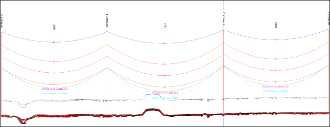
Figure 8 - 230kV Transmission Line modeled in PLSCADD
Below are some of the criteria considered for PLSCADD modeling–
-
General Loading Considerations
-
NESC heavy loading case, considering 4 psf wind at 0°F (-20°C) temperature with 0.5” ice thickness (NESC table 250-1)
-
Hurricane/Extreme Wind case considering the basic wind speed of 120 mph.
-
Concurrent wind and ice loading case considering the basic wind speed of 30 mph with 0.75” ice thickness.
-
-
Wire Tensions
-
230kV conductors are of wire type 2-959.6 kcmil Type 16 ACSS "Suwannee/ACSS/TW".
-
Design tensions are considered per NESC 2017 Rule 261-H1.
-
-
Survey Point Clearance Criteria
-
NESC Rule 232 was used to evaluate the phase-to-ground clearances for 230kV conductors and with weather criteria from Rule 232 A as follows,
-
Max. Operating Temp, 200°C (392°F) with no wind
-
-
The calculation for required clearances is as follows:
-
Per NESC 2017, table 232-1, vertical clearance to roads for 230kV = 22.5 ft The model consists of 6 different edits as follows,
-
Base Line Edit with structures having V-string insulators. The observed clearance to ground violation is 18 ft which is 4.2 ft less than the required clearance.
-
Remediation Line Edit 1 with the V-string insulators replaced by suspended dead-end insulators.
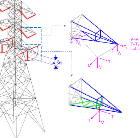
Figure 9 - Tower with Floating Dead-end modeled for bottom phases
As demonstrated in figure above, some of the existing cross-arm members (shown in blue) were modified and new members were installed (shown in green). For a V-string assembly, the total load is transferred across two load application points on the tower whereas in case of the floating dead- end assembly, the load application point on the tower is singular, as demonstrated in the diagrams of Figure 9.
-
Maximum gain in clearance is limited by the geometry of the existing suspension insulator assembly, which in this case comes out to ~4.5 ft.
-
No significant change in load; member modifications demonstrated in Figure 9 are mainly due to the change in how the loads are transferred to the tower.
-
-
Remediation Line Edit 2 with the existing crossarms replaced by insulated crossarms.
As demonstrated in Figure 10, the maximum gain in clearance is again limited by the geometry of the tower. It is higher than the floating dead-end option ~5.6 ft. The original tower is designed for one sub-conductor broken wire loading. By converting the cross-arm members to an assembly of post and string insulators, the longitudinal unbalanced load acting on the insulators will need to be
verified. Insulator vendors often design these assemblies with additional insulator braces in longitudinal direction, in case of a high longitudinal load demand.
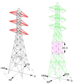
Figure 10 - Tower with insulated cross-arms (left); Tower with 20ft mid-body raise (right)
-
Remediation Line Edit 3 with the existing lattice tower modified for increased height using tower raising methodology.
As explained in the earlier sections, the tower raise operations generally are within 5 to 20 ft range. In Figure 10, 20 ft tower raise (pink section) is demonstrated. Due to the increase in the structure height, the loads in the tower will increase. Bottom leg members in the base tower (120 ft) had a maximum compression force of ~110 kips. This compressive force increased for the raised tower (140 ft) to ~ 150 kips, resulting in a ~35% increase in force. This increase will need to be evaluated on a case-by-case basis.
-
Remediation Line Edit 4 with the existing sections modified using nip-tuck fixing and using splices.
To resolve the clearance conflict of 4.26 ft, a total of 8 ft of cable lengths were slipped into the adjacent spans (4 ft in each span). Typically nip-tuck operation is implemented to resolve smaller clearance margins, hence the scenario considered in this problem statement is not ideal. Moreover, bottom phase position where nip-tuck operation is performed, experienced an increase in longitudinal load of approximately 2 kips.
-
Remediation Line Edit 5 with the existing sections replaced with HTLS conductors.
Bundled Suwannee ACSS conductors are replaced with 1582kcmil ACCC “Bittern” conductors. These conductors have 45,200 lb RBS in comparison to 33,100 lb RBS of Suwannee conductors, and hence can be sagged with lower tension limits. While the loads on the suspension structures did not change much since the weight of the conductors is comparable, the loads on dead-end structures may change due to the implementation of this option.
Table 2 summarizes the clearance values calculated with the implementation of each strategy discussed above.
|
Configuration Description |
NESC Clearance Requirement (ft) |
Clearance (ft) |
Clearance Margin (ft) |
|
Base Configuration |
22.20 |
18.00 |
-4.20 |
|
Floating Dead-end |
22.35 |
0.15 |
|
|
Insulated Cross-arm |
23.58 |
1.38 |
|
|
Structure Raise |
37.91 |
15.71 |
|
|
Nip Tuck |
22.78 |
0.58 |
|
|
HTLS Conductor |
30.52 |
8.32 |
Inferences
Table 2 – NESC Clearance Comparison Summary
|
Configuration Description |
Structure Modifications |
Other Modifications |
Engineering Checks |
Other Construction constraints
|
|
Floating Dead-end |
Members in tower cross-arm may need to be redesigned due to change in load application point |
|
structures. |
|
|
Insulated Cross-arm |
Tower cross-arms replaced with insulated cross-arms |
|
|
insulated cross-arms.
|
|
Structure Raise |
New structure members installed; new sections designed to align connections with existing bolt pattern |
|
|
they can be installed on towers with difficult access.
|
|
Nip Tuck |
|
Splice may be needed if the section is being 'nipped' |
increase; existing structures' usage to be verified |
|
|
HTLS Conductor
|
Insulator hardware needed for different conductor type
|
New conductors installed
|
need to be verified.
|
needed. |
-
Wire (including jumper loop) to structure clearances
-
Phase-to-phase clearances for a vertical/delta configuration if floating dead-end only installed on bottom phase
-
Uplift/Insulator swing for adjacent
-
Outage needed
-
Conductor may need to be offloaded for the phase where floating dead-end is installed.
-
Ability of structure to resist broken wire loads/unbalanced longitudinal loads
-
Uplift/Insulator swing for adjacent structures
-
Outage needed
-
Conductors may need to be offloaded from cross-arms during installation of insulated cross-arms.
-
Modifications to tower cage may be needed to appropriately transfer the loads from the
-
Increase in loads in existing members of tower below the new section; check existing foundation capacities
-
Uplift/insulator swing for adjacent structures
-
Modifications can be performed without taking an outage on the line, hoever, energized climbing clearances and working/climbing spaces for the tower will need to be verified.
-
Modifications are modular so
-
Section usage to ensure cable tension limits are not exceeded
-
Insulator swing
-
Phase-to-phase clearances for a vertical/delta configuration is nip-tuck is only performed on bottom phase
-
Longitudinal loads on structures may
-
Outage needed.
-
Conductors need not be offloaded from existing structures.
-
Usage of existing structures
-
Usage of dead-end structures between which HTLS conductors are installed.
-
Tension limits and section usage will
-
Longer outage may be
-
Lead times for HTLS conductor reels will need to be verified.
![]()
Table 3 - Summary of Modifications for each option along with other constraints
Different approaches to enhance electrical clearances exist, but the choice for each method hinges on a range of factors. It's important to note that in a given situation, no single method for improving electrical clearance can be definitively deemed the ultimate solution. Utility engineers are tasked with assessing all pertinent elements, as each strategy may carry diverse financial, construction, and reliability implications.