- Avinash Bingi, Assistant Division Manager
- Saurabh Harwande, Assistant Division Manager
Abstract
Accessing transmission structures at their conductor attachment locations is essential for the construction crews doing routine maintenance. OSHA Part 1910 and IEEE 1307 standards address walking-working surfaces and fall protection requirements for transmission towers and poles. However, many existing structures do not meet these requirements. This paper examines traditional fall protection measures for transmission structures, presents analysis techniques to evaluate safety fall protection systems of existing structures, and offers established best practices for engineers designing new structures. Furthermore, it explores innovative climbing approaches for inaccessible areas and unique international fall protection solutions.
Introduction
Climbing on transmission structures is necessary for structure erection, inspection, and maintenance. Step bolts have been used for climbing on transmission structures since the early 20th Century when the structures were first built. The American Bridge Corporation’s publication ‘Transmission Towers’ [5], [8] from 1925 references step bolts for climbing. Over the last century, there have been several other ways to climb and access transmission structures. Still, step bolts remain the primary option on most structures in the United States. To ensure the safety of the linemen and maintenance crew while climbing the structures, OSHA [3] and IEEE [4] have provided guidelines and standards for step bolts specifications and structure strength.
This paper will review the following six options to access transmission structures, provide a summary of climbing requirements listed in different standards, and provide innovative access methodologies used in the USA and other parts of the world.
-
Step bolts
-
Ladder Safety Fall arrest system
-
Pulley Systems
-
Bosun Chair
-
Helicopters
-
Drones
Depending upon the constraints of the project, any of these systems can be used for erection and maintenance of the transmission structures.
-
Step bolts
-
History of step bolts:
Step bolts have been used to access the structure during construction and maintenance since the beginning of the transmission structure design. Transmission tower designs evolved during the early 20th century,
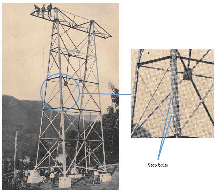
Figure 1 Step bolts on transmission tower in early 20th century
Courtesy: American Bridge Corporation’s “Transmission Towers” [5]
and step bolts became a standard feature. Figure 1 shows the step bolts on a transmission structure erected in the early 1910s. These bolts were typically made of steel and were strategically placed on the tower legs to provide climbing points for linemen. Over the years, different diameters and lengths have been used for step bolts. Some of these have bent during operations and pose safety risks for the maintenance personnel. Figure 2 below shows a bent step bolt during a routine climbing operation.

Figure 2 Bent step bolt.

Figure 3 Step bolts on a transmission pole
With the expansion of electricity grids and the widespread use of transmission towers, organizations like the American National Standards Institute (ANSI), OSHA [3], and IEEE [4] have developed guidelines and specifications for safe installation and maintenance of transmission structures, including the use of step bolts.
Step bolts were originally designed to withstand the load of the lineman and tools while climbing. The strength requirement of the step bolts was later increased to be able to withstand the climbing as well as fall protection loads.
IEEE 1307-18 [4] recommends minimum strength requirements to ensure step bolts do not bend during use. According to this standard, step bolts should meet the following criteria:
-
Minimum bolt diameter – 5/8”
-
Be capable of supporting a minimum of 598 lb load applied 2” from the face of the bolt head.
For most lattice towers, standard bolt diameters are 5/8” and 3/4". When 5/8” and 3/4" diameter step bolts conforming to ASTM A394 [6] Type 0 and Type 1 standard are checked for the above guidelines, the 5/8” diameter Type 0 bolts do not meet the requirements. Calculation results are shown below in table 1.
To ensure the step bolts meet the strength requirements as per ASTM A394-08 [6], they can be tested in the lab. Figure 5 and Figure 6 show the mechanical shear and tensile tests.

Table 1: Comparison of bending strength for step bolts with ASTM A394 Type 0 and Type 1 grades [6].
5/8” A394 Type 0 bolts do not satisfy the bending strength requirements.
Step bolt type
Diameter (in)
Length of step bolt (in)
Moment arm
(in)
Max. Tensile
Stress (ksi)
Section modulus
(in3)
Bending stress
(ksi)
A394-T0
5/8
6.5
4.5
74
0.024
113
A394-T0
3/4
6.5
4.5
74
0.041
65
A394-T1
5/8
6.5
4.5
120
0.024
113
A394-T1
3/4
6.5
4.5
120
0.041
65
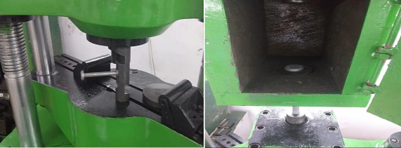
Figure 6 Shear Load Test Figure 5 Tensile Load Test
As per OSHA 1910.24(a)(9) [3] and IEEE 1307-18 (Section 10.1.1(e)) [4] recommendations, any step bolt that is bent more than 15 degrees from the perpendicular in any direction should be replaced.
-
-
Fall Protection Requirements.
OSHA [3] recommends that anchorages used for attachment of personal fall arrest equipment should be independent of any anchorage being used to support or suspend platforms and capable of supporting at least 5,000 lb (22.2 kN) per employee attached. Since April 2015, OSHA (29 CFR 1910) [3] has mandated that each employee climbing or changing location on transmission structures always use fall protection. Step
bolts are typically installed on all structures can be attachment points for safety equipment, such as personal fall arrest systems or positioning lanyards while working or climbing on the structure. Hence, the step bolts need to be designed to withstand 5,000 lbs. of fall protection load.
Regular step bolts are weak in bending and cannot withstand the 5,000 lb fall protection load in bending. However, these bolts can be modified using an anchor flange to help transfer the fall protection load to the step bolt in shear. Step bolts are very strong in resisting shear force and should be able to withstand this load. Figure 7 shows a regular step bolt, whereas Figure 10 shows the step bolt modified with an anchor flange.
Alternatively, the step bolts can be manufactured with a ‘D Ring’ (Figure 9) for attaching the fall protection harness.
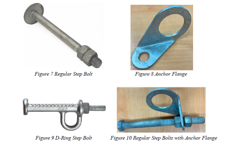
Photo Courtesy: Buckingham Manufacturing
Generally, the step bolts with a D-ring or anchor attachment are used as an anchor attachment point while climbing the structure. However, at some leg splice locations, the anchor attachment might interfere with the structure members (Figure 11). In such cases, installing this step bolt on a plate outside the main splice connection is recommended, as shown in Figure 12. If step bolts are installed on a plate, the plate must be checked to ensure it can transfer the fall protection load in bending. In the example shown in Figure 12, a 1/4" plate connected to three bolts on the leg splice satisfies the bending strength requirements.

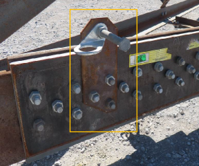
Figure 7 Step bolt with anchor flange is provided because of the interference with another member
Figure 8 Step plate at the butt splice location
Step bolts on lattice structures are usually located on one leg, but they may be provided on two or all four legs depending on the utility’s requirements.
On splice locations, replacing a regular bolt with step bolts may be required. In such cases, it is important to consider the shear strength of the step bolts. The special step bolts with a D-ring satisfy the fall protection load requirement of 5000 lbs; however, they may not meet the shear strength requirements of the regular tower bolt they are replacing. In such cases, a regular step bolt with the same strength as tower bolts is recommended.
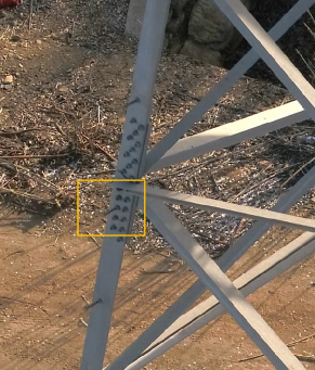
Figure 13 Step Bolt used in lieu of regular bolt. In this case, step bolt strength should match the tower bolt strength.
While step bolts offer certain advantages, attaching and detaching harnesses at multiple locations while climbing is challenging for the linemen.
-
Fall Protection Checks for Lattice Towers:
Once we ensure that the step bolts are capable of withstanding fall protection loads, it is important to ensure that the structure can withstand the code-mandated fall protection load of 5000 lb. To check the strength of the lattice towers, a new load case should be created with a vertical dead load of 5000 lb. for each attachment point in conjunction with the construction loads applied on the conductor attachment points.
Many of the old lattice towers may not be able to withstand this load. A construction drawing marking various points with safe and unsafe attachment locations should be created. IEEE 1307-2018 [4] provides guidelines for reducing the fall protection loads in case energy absorbing lanyards are used. In this case, the 5000 lb. load can be reduced and should be marked on the drawing. An example of the fall protection drawing with safe attachment points is shown in Figure 14.
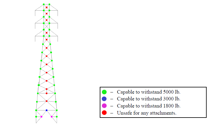
Figure 14 Tower fall protection drawing indicating safe attachment points.
If the step bolts do not have a fall arrest anchor point, it is possible to attach the lanyard to tower members. These locations will need to be checked in the analysis but nodes on the leg member with multiple member connections will be the strongest attachment points.
During climbing and maintenance activities, tower members may be used to support the maintenance personnel. These members will need to be checked for flexure due to the weight of the workers.
According to ASCE 74 [2], the members should be able to withstand a vertical load of 375 lb (including a minimum load factor of 1.5). Angle members are very strong in axial capacity and weak in bending capacity. The flexural capacity of the angle should be checked according to equation 3.14.7 from ASCE
10-15 [1]. An eight-foot 2x2x3/16” angle has an axial capacity of 4.70 kips but cannot withstand 375 lbs load in bending.
-
-
Ladder Safety Fall Arrest System
Ladders are commonly used for climbing on the lattice towers. Some old towers also include stairs in the center of the tower for climbing. Figure 15 below shows a tower with stairs at the center of the tower. Ladders along the tower leg are common on structures above 200 ft in height, as seen in Figure 16. It is common to have a cable safety system installed along with the ladders on these towers. It is common for tall river crossing towers to have rest platforms at regular intervals to allow the worker to get off the ladder and rest.
Figure 15 Tower with stairs installed at the centre of the tower.
Figure 16 River crossing tower with a ladder along the tower leg and platforms at regular
intervals.
Ladder safety systems typically consist of a vertical lifeline (Cable safety system) attached to the ladder at the top and bottom. It uses cables to secure a worker. This mechanism can arrest a fall if a worker slips while climbing a ladder. Figure 18 shows examples of cable safety systems.
Bonneville Power Administration had recommended a horizontal lifeline for walking across the tower in 2015 (2015 O’Claire et al, [7]). The system is shown in Figure 17.

Figure 17 Horizontal Lifeline for walking across towers. (O'Clair D. et al. [7])
Based on OSHA’s [3] regulations #1910.28(b)(9)(i)(D), newly installed or existing vertical access ladders of 24 feet or more will be required to have a personal fall protection system or a ladder safety fall arrest system installed, thereby replacing the cages, before November 2036.
One of the limitations of this system is that only one person can use the system at a time unless manufacturer rating allows for more.


Figure 18 Worker climbing on step-bolts using the cable-based safety system.
Courtesy: Engineered Fall Protection
Courtesy: Flexible Lifeline Systems
There are products in the market that can be used to retrofit an existing structure with fall protection ladders. Figure 19 shows one such system used in Europe. This system can be attached to an existing transmission structure (lattice tower or tubular steel pole) without any need for drilling holes. This system has an inbuilt
fall protection system and does not require an additional cable safety system. Figure 19(b) shows the details of this system installed on the tubular structures. Figure 19(c) shows the details of this system installed on the lattice towers.


(a)
(b)
(c)
Figure 19 (a) Saferail Ladder with built in fall protection system. (b) Saferail system installed on a
pole. (c) Saferail system installed on a lattice tower.
-
Pulley Systems
If the terrain does not allow for a bucket truck access to the structure, but the structure is strong enough to withstand the fall protection loads, it is possible to design a pulley arrangement which can be used to hoist equipment like insulators and people up the transmission structure.
The structure analysis should check for structure strength due to conductor loads for construction load case, fall protection loads as well as pully loads applied on the structure simultaneously.
Figure 20 shows a pulley system used to hoist a construction worker up to maintain guy wires. The same system can be used to hoist insulators and other maintenance equipment up the tower.

Figure 20 Person lifted by using pulley systems for maintaining the guy wires.
-
Bosun Chair
A bosun's chair is a device used to suspend a person from a rope to perform work. It is a simple and effective system that can be used in a variety of settings.
The bosun's chair consists of a seat, a harness, and a rope. The seat is typically made of canvas or webbing, and it is attached to the rope with a series of knots or clips. The harness is worn around the worker's waist and shoulders, and it provides a secure attachment point for the rope. Bosun's chair is used to suspend the worker from the rope. The rope is attached to a secure anchor point on the structure or a helicopter. The rope is then used to raise or lower the worker as needed. One of the benefits of this method is that it is possible to pick a point on the tower that is safe to resist fall protection loads for securing the rope to the structure vs climbing the structure that will require a check for multiple attachment points.
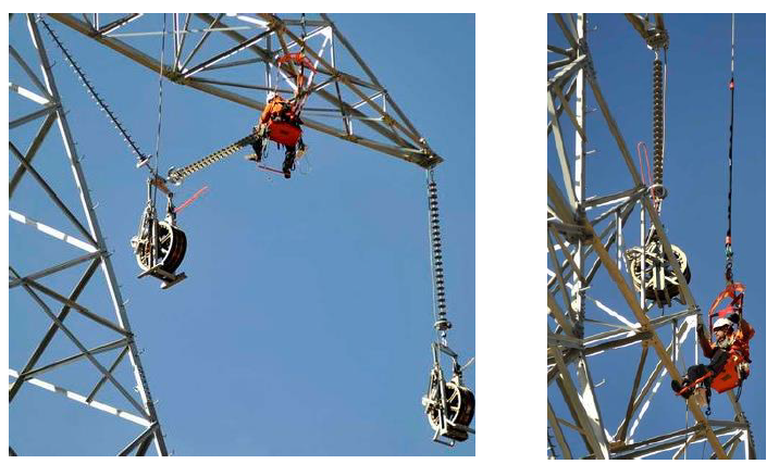
Figure 21 Worker in a bosun chair inspecting a transmission tower
Courtesy: Amarillo Globe-News
-
Helicopters
A helicopter may be used to lift a person up to the structure, where they can perform work. This technique can be used to install cables, inspect the structure, or perform maintenance. Moreover, it reduces the project execution time and shortens the transmission line shutdown time. It can be used to access structures in a variety of locations, including those that are difficult to reach by road due to remote locations or environmentally sensitive ecosystems. Use of helicopters also minimizes the need for heavy machinery and other vehicles on the ground along the alignment.
However, this being a specialized job, stringing conductor wires to transmission structures using helicopters requires extreme precision and stability. A detailed risk assessment for the scope of work should be completed, and emergency response capability that is unique to the work location must be identified and confirmed.

Figure 22 Helicopter used to clean the insulators

Figure 23 Helicopter used to string the conductors
Courtesy: Vertical mag
-
Drones
Drones are increasingly being used for a variety of tasks in the power industry. They started out as an inspection tool to take photos of the structure without climbing it. Lately they are also used for stringing conductors on transmission structures. Due to the increase in the use and production of drones catered to the utility industry, they are becoming more affordable for various operations.
Drones have several advantages. Drones can fly over obstacles and difficult terrain, which eliminates the need for workers to climb towers or cross dangerous lines which reduces the risk of accidents. The structure in Figure 24 below has a damaged insulator attachment connection photographed by a drone. Due to the nature of the damage, it is not safe to climb this structure for inspection. Drones can string conductors much faster than traditional methods, which can save time and money. Figure 25 shows the stringing operation using drones. Drones produce less noise and emissions than helicopters, which makes them a more environmentally friendly option.
However, there are also some challenges associated with using drones for stringing conductors. Drones cannot fly in strong winds or rain, which can limit their use in certain areas. Drones may not be able to fly over mountainous terrain having highly dense vegetation or other obstacles. They do need a ground escort to drive along the right of way.
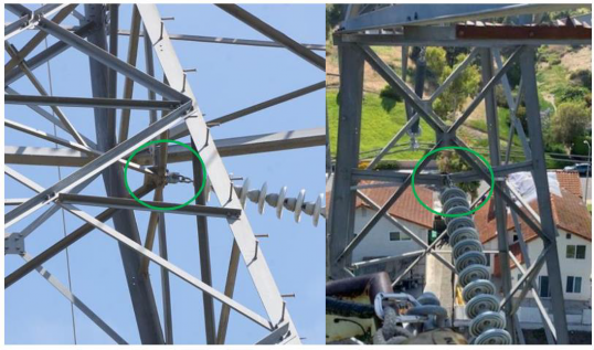
Figure 24 Close up photos of damaged insulator attachment. It is not safe to climb the structure to inspect this tower. Drones can make it possible in such scenarios.

Figure 25 Stringing of conductors using drones.
Courtesy: Dronelife
References:
-
ASCE 10 (2015) - "Design of Lattice Steel Transmission Structures". ASCE 10-15, Reston, VA.
-
ASCE 74 (2020) - "Guidelines for Electrical Transmission Line Structural Loading." ASCE 74-20, Reston, VA.
-
Occupational Safety and Health Administration 1910 & 1926
-
IEEE 1307 (2018) – “Standard for Fall Protection for Electric Utility Transmission and Distribution on Poles and Structures”
-
American Bridge Corporation's "Transmission towers"
-
ASTM A394 (2008) – “Standard Specification for Steel Transmission Tower Bolts”. ASTM A394-08
-
David E. O’Clair, David M. Hesse (2015). "Fall Protection Efforts for Lattice Transmission Towers" Electrical Transmission and Substation Structures 2015.
-
Deshmukh, P. (2022). "Challenges in Analysis of 100-Year-Old River Crossing Structures" Electrical Transmission and Substation Structures 2022, 259-269.