Sanchit Chitre, P.E.
Manager of Engineering, ASEC Engineers. [email protected]
Abstract
Construction operations that involve the application of loads during wire removal can be of significance for existing transmission towers. Suspension towers are conventionally designed for code-specified and broken wire load cases but may not be designed for wire unloading operations. Moreover, the sequence in which the wire is offloaded from an existing tower can thereby alter the load flow within the tower members. In cases where there are concerns about the integrity of the structural members and the foundations, determining the most appropriate sequence is crucial for utilities.
This paper examines construction equipment used for wire removal to understand its impact on tower loading. Subsequently, two (2) 230kV double circuit transmission line scenarios are considered to assess the unloading sequence parameters. The findings from this study aim to guide project engineers in conducting necessary checks and verifications when managing wire unloading for existing towers.
1. Introduction
There is a need to upgrade utility infrastructure to meet the increasing energy demand. However, as transmission lines approach or exceed their design life, aging transmission infrastructure presents a significant challenge for utilities worldwide. Aging transmission infrastructure poses a significant challenge for utilities worldwide.
Wire loading and unloading are essential components of upgrading transmission infrastructure. The ASCE 74 manual of practice, "Guidelines for Electrical Transmission Line Structural Loading," emphasizes the importance of understanding loads due to wire installation and removal. It highlights that ground wire and conductor stringing loads may exceed the anticipated maximum intact design loads and should be calculated based on stringing geometry and the length of wire pull.
Materials used in older transmission structures may have deteriorated over time, foundations
may have settled or shifted, and overall structural integrity may have been compromised by environmental factors and repeated loading cycles. While these structures behave normally under all-wires-intact loads, they may lack the strength to withstand the unbalanced loads experienced during stringing or wire removal activities. Although ASCE 74 does not specifically outline the loading considerations due to wire removal or unloading, they can be simulated using finite element analysis to understand their impact on structure strength.
This paper aims to provide an overview of the construction equipment used for wire unloading and its impact on structure loads. The study explores two scenarios involving a 230kV double-circuit transmission line to develop a wire unloading sequence. The first case study involves the unloading of all wires on a dead-end structure with compromised foundations that cannot withstand any unbalanced loads. The second case study examines use of a suspension tower to ‘dead-end’ the conductor, as environmental restrictions prevent restringing operations from extending to the nearest dead-end tower three
miles away. The findings from this study are intended to guide project engineers in conducting the necessary checks and verifications to manage wire unloading operations effectively for existing transmission towers.
2. Construction Equipment
Effective management of transmission line maintenance and upgrade operations requires a comprehensive understanding of the various construction equipment used and their impact on existing transmission structures. The "IEEE 524- 2016 Guide for Installation of Overhead Transmission Line Conductors" provides detailed insights into these equipment types and their operational implications. This section expands on these definitions to illustrate how different construction tools and machinery can affect the loading conditions of transmission towers.
2.1 Hoist
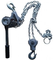
Figure 1 - Aluminum Alloy Chain Type Handle Hoist
[3]
A hoist is an apparatus designed to move a load by applying a pulling force, typically using roller or link chains and built-in leverage to lift or pull heavy loads. In transmission line operations, hoists are frequently utilized to dead-end conductors during sagging and clipping-in processes, as well as during the tensioning of guy wires. The application of hoists introduces significant vertical and longitudinal loads on the structures. These loads can temporarily exceed
the design specifications, causing stress concentrations that may affect the integrity of the tower members, especially in older towers. Hoists should be attached to tower members at locations that are designed to take full conductor loads. Hence it is essential to not only check the structure but also the strength and capacity of the local members where loads are applied.
2.2 Snatch Block
A snatch block, also known as a skookum, is a single sheave typically made of metal or wood and has a hook or a shackle at one end. It is typically used for lifting loads on a single line or to position a pulling line.
2.3 Pilot Line
Pilot lines, also known as lead lines or straw lines, are lightweight lines often used to pull heavier pulling lines. Pilot lines are often installed with the aid of lead lines or helicopters, particularly when insulators and travelers are already in place. Although pilot lines themselves exert minimal loads on the structures, the subsequent pulling lines and conductors they facilitate can introduce substantial tensile forces. The installation process, especially when conducted via helicopter, may also impart dynamic loads and stresses on the structure due to the movement of the wires. [1]
2.4 Pulling Line
A pulling line or hard line, typically made of high- strength synthetic fiber rope or wire rope, is used to pull the conductor into position. In reconductoring projects, the old conductor might serve as the pulling line for the new conductor, necessitating a thorough inspection to ensure it can handle the required loads. The use of pulling lines introduces significant longitudinal forces on the transmission towers. These forces can create complex load conditions, particularly when the pulling operation involves changes in direction, leading to additional transverse and vertical loads that the structure must support.
2.5 Traveler
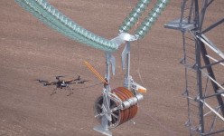
Figure 2 – Drone used to pull a pilot line across the traveler [4]
A traveler or a stringing block is a sheave assembly used to facilitate the stringing of conductors. These devices are often bundled to string multiple conductors simultaneously and are lined with nonconductive or semiconductive materials such as neoprene or urethane to protect the conductors from damage. The use of travelers involves the suspension of conductors from the structures, which imposes both vertical and horizontal loads. The weight of the conductors and the dynamic forces during stringing, especially due to the conductor getting caught in the block, can significantly impact the longitudinal loading on the structure, necessitating careful consideration to avoid overloading the suspension points and the tower members.
2.6 Bullwheel Tensioner
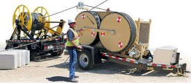
Figure 3 - Tensioner unit with a V-groove
A bullwheel tensioner is a device designed to maintain tension against a pulling line or conductor during the stringing phase. It typically consists of power-braked, urethane-or neoprene- lined bullwheels arranged in tandem, creating tension through friction. Bullwheel tensioners
can introduce substantial longitudinal and transverse loads on the structures due to the tensioning force required to string the conductors. Additionally, the mechanical or hydraulic retardation mechanisms used in these devices can create dynamic loading conditions that must be accounted for during the design and planning of the operation.
2.7 Crawler Tractor
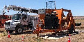
Figure 4 - Sag Cat or Crawler Tractor
A crawler tractor, also known as a cat, or a sag cat, is a tracked unit employed to pull pulling lines, sag conductors, level or clear pull and tension sites, and perform miscellaneous other work. It is also frequently used as a temporary anchor. The sagging winches on this unit are usually arranged in a vertical configuration. The use of crawler tractors introduces significant ground-level forces that can affect the stability of the structures. When used as a temporary anchor, the tractor must be securely positioned to avoid shifting, which can create uneven loading on the transmission towers. Additionally, the leveling and clearing operations performed by crawler tractors can cause ground vibrations and disturbances, potentially impacting the foundation stability of nearby structures.
2.8 Impacts on Existing Structures
The use of these construction equipment types introduces various loading conditions that can affect the structural integrity of existing transmission towers. Key impacts include:
- Vertical Loads: Equipment such as hoists and travelers introduce significant vertical loads, especially during dead-ending and stringing operations. These loads can exceed the design specifications of older towers, potentially leading to deformation or failure of structural members.
- Longitudinal Loads: Pulling lines and bullwheel tensioners exert longitudinal forces that can affect the stability of the towers. The magnitude and direction of these forces need careful consideration to prevent undue stress on the structure.
- Transverse Loads: The pulling and stringing processes can introduce transverse loads, particularly when lines are pulled at angles. These loads can create bending moments and shear forces in the tower members, which must be managed to avoid structural compromise.
By understanding the specific impacts of each type of construction equipment, project engineers can better plan and execute maintenance and upgrade operations, ensuring that the loading conditions imposed on the transmission towers remain within safe limits. This comprehensive analysis is essential for maintaining the reliability and safety of aging transmission infrastructure.
3. Case Study 1: Wire Unloading on Existing Towers set to be Replaced
3.1 Overview
This project involved the critical task of replacing four existing transmission towers on a 230kV double-circuit line. The towers, identified as #100, #150, #200, and #250, required a systematic unloading sequence of the conductors to ensure the stability and integrity of the structures during the replacement process.
- Span Configuration: The first and last spans are approximately 1000 feet each, while the middle span (#150 - #200) is a long span crossing over a transportation corridor.
- Tower Heights: Structures #100 and #250 are dead-end towers of 100 feet height, while Structures #150 and #200, which facilitate the crossing, are tall suspension towers approximately 200+ feet tall. Structure #250 has a 20 deg line angle.
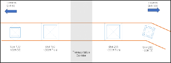
Figure 5 – Plan View of tower locations
- All four towers need to be replaced, and the conductor upgraded as part of a system-hardening project. Following activities are required to be completed,
- Unload the existing wires from existing towers between #100 and #250
- Install and erect new foundations and structural steel for proposed replacement towers #100, #150, #200 and #250.
- Remove existing towers.
- String new conductors on replacement towers between #100 and #250.
3.2 Project Constraints
Following constraints were present which will need to be addressed when coming up with the construction sequence for completing the activities described in the above section,
- Constraint 1 - Adjacent structures (Structure #50 and Structure #300) do not have the capability to withstand unbalanced longitudinal loads. The loads acting on adjacent existing structures should not change during wire unloading.
- Constraint 2 - Field inspection of towers #100 and #250 indicated surface damage to the tower foundation caps. Even though the structures were originally designed for all wires broken conditions, the wire unloading sequence should not impose any unbalanced load on the structures.
- Constraint 3 - The wires over the span between structure #150 & #200 should always maintain at least 50 feet of clearance above the transportation corridor below. This necessitates maintaining a minimum tension in the wires even during the wire removal operation.
3.3 Mitigation of Project Constraints
Following construction sequence is adopted to unload the wires and install new towers,
Proposed replacement tower #250 is designed and its location is selected such that the conductor attachment points on the new tower are at similar elevations as the existing wire elevations, as shown in Figure 6 below. This design strategy allowed to limit the change in the loads acting on adjacent tower #300. This helped mitigate Constraint #1.
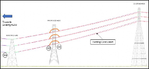
Figure 6 - Rigging of Hoists H1, H2, H3
- To help maintain the existing wire tensions on the span to Existing #300, hoists were utilized. Following steps were undertaken:
- Hoists were installed (H1, H2, H3 shown in Figure 6 above) at proposed tower #250.
- Rig hoist H1 on the ahead span of proposed tower #250 towards existing structure #300 to hold the conductor tension. This helps hold the existing tension of the wire towards Existing Str. #300, and hence helps mitigate Constraint #1.
- Rig hoist H2 on the back span of proposed #250 towards existing tower #250 to hold the conductor tension.
- Rig hoist H3 on the back span of existing tower #250 towards existing tower #200 to hold the conductor tension.
- Dead-end the wires between proposed tower #250 and structure #300 at the proposed structure #250.
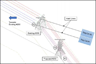
Figure 7 - Hard line pulled into Sag Cat
- To help maintain the load balance between ahead and back spans of the dead-end towers, hoists were rigged and hard line was pulled into sag cat to maintain the wire tensions of the crossing span. Following steps were undertaken:
- Sag cats were set up 500 ft behind the existing tower #250.
- Pull hard line to the sag cat by existing tower #250, as shown in Figure 7 above. In this step, ahead and back span phase conductors are moved from existing #250 one at a time.
- Hoist H3 is used to gradually reduce the load on back span of the Existing Str #250 and transfer the load to the Sag Cat. At the same time, Hoist H2 on the new Proposed str #250 is used to lower the load on the ahead span of Existing Str #250 and transfer it to New Proposed Str #250.
- This process allows maintaining balanced loads on the existing tower #250.
- Hoists H2 and H3 rigged in tandem along with the use of the proposed tower #250 helps maintain balanced loads on existing #250 as the wire is offloaded from the tower and the tension is held by the sag cat.
- In this fashion, each phase wire is offloaded from the existing tower #250.
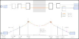
Figure 8 - Wire unloading set-up for the project
- Similar operations were performed at Tower #100 location. These steps helped offload the wires off the critical towers #100 and #250 with the use of Sag Cat equipment on the right and the tensioner unit on the left, as shown in Figure 8 above. These steps helped mitigate Constraint #2.
- To help maintain a minimum clearance above the corridor crossing, sag tension values were calculated at the construction weather condition, as reported in Table 1 below. This allowed the construction contractor to determine the pulling tension for executing the wire removal operations. This helped mitigate Constraint #3.
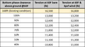
Table 1 - Sag-Tension Values for Crossing Span
3.4 Other Considerations
There were several analysis considerations in the project to facilitate the wire unloading -
Construction Load Case
Existing towers are analyzed for the unloading sequence for the construction weather condition of 60°F with 3psf wind, per ASCE 74-2020. An overload factor of 1.5 was considered for the tower analysis. Wind speed varies with the height of the towers. Exposure category D was considered for the analysis.
Unloading Sequence
One of the constraints imposed due to construction operations was that bottom phase wires shall be unloaded first. There were two possible sequences. Analysis results were compared to determine the preferred sequence (the one shown on right in figure below).
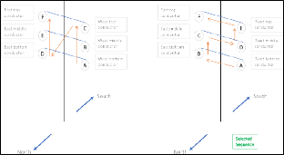
Figure 9 - Unloading Sequence Options
Loading Configurations for Tangent Crossing and Dead-end Towers
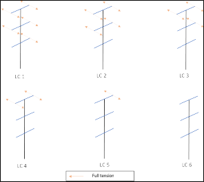
Figure 10 - Loading Configurations for Dead-end Towers #100 & #250
Based on the activities described in Section 3.2 for towers #250 and #100, the use of hoists and sag cat helps maintain the ahead and back span tensions at a phase as the wire is offloaded from the tower. Based on the selected sequence shown in Figure 9, above loading configurations are analyzed for towers #100 and #250 shown in Figure 10.
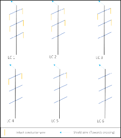
Figure 11 - Loading Configuration for River Crossing Towers #150 & #200
Similarly, the loading configurations shown in Figure 11 are used to analyze towers #150 and #200. The results of the analysis were used to ensure the foundation reactions during the construction sequence on the existing dead-end towers did not exceed the values from all wires intact load case.
This case study provides a comprehensive overview of the unloading sequence analysis. The findings highlight the importance of a systematic approach to wire unloading operations, especially for aging transmission structures. By meticulously planning and analyzing each step, project engineers can ensure the safety and reliability of the towers during maintenance and upgrade activities. The insights gained from this study serve as a valuable guide for similar projects, emphasizing the need for detailed analysis and careful execution to maintain the structural integrity of transmission towers.
4. Case Study 2: Reconductoring on Existing Towers set to remain in place
4.1 Overview
This project involved the replacement of damaged conductors between structures #10 and #40 on a 230kV double-circuit transmission line. The project required a thorough structural analysis to determine the necessary construction sequencing and modifications to ensure the safe replacement of the conductors while maintaining the integrity of the existing towers.
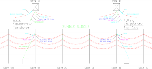
Figure 12 - Profile view of Reconductoring Operation
230kV double-circuit transmission line has a double bundled conductor, Ortolan 1033.5 ACSR/AW. The transmission line has a single shield wire, 7#10 Alumoweld. Six towers will be affected by the scope of this construction, #10A, #10, #20, #30, #40, #50, as shown in Figure 12 above. All six towers are double-circuit tangent towers. There is no dead-end tower adjacent to these structures; hence, it was decided to perform the stringing operation by temporarily dead- ending on structures #10 and #40. The suspension towers were originally designed for single bundle broken conductors under NESC Light loads with a load factor of 1.0.
Loading Considerations
Structures were analyzed using the existing tension of 6,500 lb at 60°F and 3psf wind. Stringing cases were run at 100% of existing tension to anticipate the possibility of existing tensions being held under the snubbing configuration. Structures are analyzed for only one sub-conductor broken at a time.
Structures were analyzed for following load cases,
- Construction Loads: Str# 10A & #50
- 60°F, 3psf wind, broken wire in the ahead span toward Str #10 (Load Factor 1.5)
- Construction Loads: Str# 10 & #40
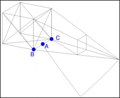
- 60°F, 3psf wind, single sub-conductor (1) intact in tower cage point A, sub-conductor (2) ahead and back span dead-ended in tower cage point B & C, with rigging loads (Load Factor 1.5), shown in Figure 13.
- 60°F, 3psf wind, single conductor (1) intact in tower point A, stringing new ahead-span conductor at a 2:1 slope in-line toward Str# 10A at point A, existing back span of conductor (2) dead-ended in tower cage point B, and with rigging loads (Load Factor 1.5), shown in Figure 13.
- 60°F, 3psf wind, both conductors (1) and (2) intact in tower point A, with rigging loads (Load Factor 1.5).
- All the above stringing load cases were analyzed at 100% of the design tensions.
- All wires intact on V-string, 60°F, 3psf wind, with and without rigging loads (Load Factor 1.5, Vertical Load Factor 2.0).
- Construction Loads: Str# 20
- 60°F, 3psf wind, 150% sub-conductor longitudinal load imbalance on the structure to account for the conductor getting caught inside the bundle block with rigging loads (Load Factor 1.5).
- All wires intact on V-string, 60°F, 3psf wind, with and without rigging loads (Load Factor 1.5, Vertical Load Factor 2.0).
- Construction Loads: Str# 30
- 60°F, 3psf wind, 150% sub-conductor longitudinal load imbalance on the structure to account for the conductor getting caught inside the bundle with rigging loads (Load Factor 1.5).
- All wires intact on V-string, 60°F, 3psf wind, with and without rigging loads (Load Factor 1.5, Vertical Load Factor 2.0).
- Rigging Loads: Structures #10A, #10, #20, #30, #40 and #50.
- 60°F, 3psf wind, with and without rigging load of 450 lbs (Load Factor 1.5).

Figure 14 - Addition of Bracing Members
Because of the increase in vertical loads in the towers, a common failure mode observed in tangent towers is compression failure due to the
tower legs’ L/r capacity. To increase the L/r capacity of the tower legs, bracing members can be added to reduce the unbraced length, as shown in Figure 14. These modifications can be installed without provision of external support and without unloading the wires off the tower.
Figure 13 - Crossarm Isometric View
4.3 Tower Modifications
Rigging loads increased the vertical loads previously subjected on the tangent towers. Hence, most of these towers required reinforcements. Similarly, towers #10 & #40 required additional modifications in the towers’ legs in the cage portion. These modifications were required to be installed prior to the reconductoring operations.
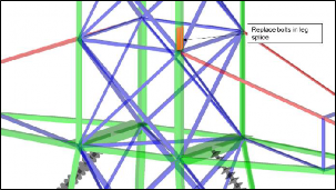
Figure 15 - Bolt Replacement in Leg Splice
Due to the longitudinal loads from one broken sub-conductor, there is an increase in the tension forces within the cage leg member controlled by its connection shear capacity. To mitigate this overstress, bolt replacement in the leg splice is recommended for Structures #10 and #40, as depicted in Figure 15. Figure 16 below shows the bolt replacement sequence replace all eight (8) bolts of the leg splice one at a time.
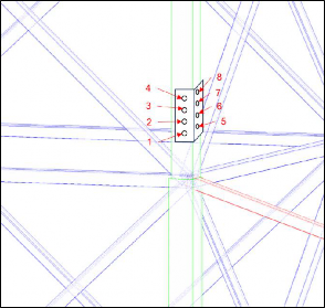
Figure 16 - Bolt Replacement Sequence
4.4Foundation Summary
To determine the effect of the construction sequence on the foundations, the foundation reactions from the construction loads were compared to those obtained from the original design loads. All tower heights for the tangent tower type were analyzed for maximum design loads for all design load cases. The in-situ foundation reactions were obtained for each of the six structures for the construction load cases.

Table 2 - Design Foundation Reactions for Tangent Tower Type

Table 3 - In-situ Reactions for each Tower during Construction
Comparing the reaction values above, foundation reactions for the in-situ construction loads are less
than the design foundation loads of the tangent tower type.
4.5 Traveler or Bundle Roller Attachment Position
In discussion with the construction contractor, potential bundle roller attachment positions were determined on the tower that would facilitate the wire removal and stringing operations without imposing unnatural loads on the tower causing local or global failures in the structures. Each option was carefully assessed with the use of engineering calculations and accordingly, the most appropriate attachment position was agreed upon.
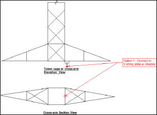
Figure 17 - Bundle Roller Attachment Option 1
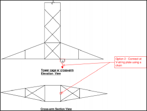
Figure 18 – Bundle Roller Attachment Option 2
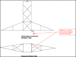
Figure 19 - Bundle Roller Attachment option 3
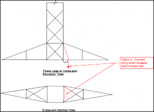
Figure 20 - Bundle Roller Attachment option 4
Three primary engineering calculations were performed to determine which of the above options can be selected to attach the bundle roller.
- V-string attachment plate is checked for bending loads due to the vertical and longitudinal loads from the conductor. Transverse loads produce shear force in the plate.
- V-string attachment plate is connected to the tower angles using welded connections. Weld thickness will need to be checked to ensure the eccentric loads subjected on it don’t cause overutilization.
- The cross-arm strut member where the V-string plate attaches is checked for bending; treated as a simply supported beam with a point load acting at the center.
Based on these calculations, attachment option 2, shown in Figure 18, was selected for attaching the bundle roller.
The Tangent Tower Reconductoring Project successfully identified and addressed the structural challenges associated with replacing damaged conductors on the 230kV transmission line. Through detailed analysis and strategic modifications, the project ensured the structural integrity and safety of the towers during the reconductoring process. This case study highlights the importance of thorough planning and collaboration in managing complex transmission line projects.
The results of this project emphasize the critical need for comprehensive structural analysis and carefully planned construction sequences to mitigate risks and ensure the safety and reliability of transmission infrastructure. By applying both standard and custom modifications, the project team effectively addressed the overstresses, ensuring the successful completion of the reconductoring process without compromising the structural integrity of the towers.
5. Key Inferences
- Critical Impact of Unloading Sequence on Structural Integrity: The sequence in which wires are unloaded from transmission towers significantly influences the load distribution within the structure. Inadequate planning and execution of wire unloading can lead to unexpected stresses and potential structural failures, particularly in aging infrastructure. Proper sequence determination is crucial for maintaining the integrity and stability of transmission towers during maintenance and upgrade operations.
- Importance of Construction Equipment in Load Management: Various construction equipment used during wire unloading operations, such as hoists, snatch blocks, and bullwheel tensioners, introduce different types of loads (vertical, longitudinal and transverse) on the transmission structures. Understanding their impact is essential to keep loading conditions within safe limits and prevent structural damage.
- Case Study Insights on Unloading Operations: The case study involving a 230kV double circuit transmission line highlights the complexities and critical considerations of wire unloading operations. By analyzing the optimal sequence for wire removal, the study demonstrates how systematic planning and precise execution can mitigate adverse impacts on structural integrity, ensuring safety and reliability during the process.
- Necessity of Detailed Structural Analysis: Conducting detailed structural analyses for different loading scenarios and weather conditions helps in identifying critical steps and planning necessary mitigations to maintain structural stability.
- Foundation Considerations and Augmentation: The study emphasizes the importance of evaluating foundation strength before construction and maintaining foundation loads within capacity during wire unloading operations.
7. References
1. Institute of Electrical and Electronics Engineers IEEE 524-2016 Guide for Installation of Overhead Transmission Line Conductors
2. American Society of Civil Engineers ASCE 74-2020, Guidelines for Electrical Transmission Line Structural Loading
4. Wire_Unloading_Sequence by SkySkopes, https://dronelife.com/2020/03/19/dronelife-exclusive-how-drones-will-change-power-line-stringing-forever/

