
1. Abstract
The transmission line engineering industry is changing faster than it ever has before. With the increased usage of Computer Assisted Design (CAD), more accurate and efficient analysis processes are created every day. Combining this with the possible increase of liability profile from regulatory bodies, many utilities are evaluating ubiquitous industry standards to stay up to date with modern design practices. A particular area of focus for utilities is increasing the reliability of at-risk assets in extreme wind and/or high fire threat zones. The aim of this paper is to explore the suitability of engineered direct embedded structures (foundations) to increase the reliability of at-risk transmission assets. A direct embedment foundation is a pole foundation where the pole is embedded directly into the ground. An engineered direct embedment foundation is distinct from a standard direct embedment foundation because it is designed from scratch using on-site soil conditions and calculated loads rather than assumptive soils and loads.
Engineered direct embedded foundations are typically utilized in areas with poor soil such as wetlands or marshes due to foundation equipment access limitations. Traditionally, standard direct embedded foundations use the industry standard of 10% of the pole length + 2 ft for embedment depth. For poles with higher moment capacities, utilities may choose to install with a higher default embedment, for example, 10% + 6 ft embedment depth. While these standards have been used successfully across industry for decades, they only provide a certain level of reliability which may not meet the level of reliability need for at-risk assets. Engineered direct embedded foundations can provide an increased structure reliability without the prohibitive costs of something like a traditional drilled pier foundation.
This paper will provide a comprehensive overview of the pros and cons of engineered direct embedded foundations for the application of increasing the reliability of at-risk assets. It will discuss the possible assumptions, parameters, methodologies, foundation design software and design considerations for engineered direct embedded foundations. Finally, it will compare three different analyses of the industry standard 10% + X ft embedment depth versus example CAD derived direct embedment depths.
2. Problem Statement
An increasingly prominent focus in industry is currently on at-risk overhead assets. These assets are exposed to adverse conditions which decreases the reliability of a transmission system as a whole. Adverse conditions can include high fire threat risk or extreme winds such as hurricanes. The purpose of this paper is to analyze the pros and cons of engineered direct embedment design versus different standard embedment methodologies with respect to increasing reliability for at-risk assets. This study will be using PLS-CADD and MFAD for the analysis and will be focusing on monopoles. Direct embedment foundation design can be analyzed using pole loading calculators & foundation software, but those methodologies are not included in this paper. The PLS-CADD & MFAD methodology to be discussed are as follows:
- Calculating induced ground line foundation reactions for monopoles using PLS-CAD
- Detailing geotechnical MFAD parameters used in the analysis using
- Setting direct embedment foundation performance criteria in MFAD
We will compare the following three direct embedment design methodologies:
- Conservative Standard Embedment – Designed to handle high loads with poor soils
- Average Standard Embedment – Designed to handle average loads with average soils
- Direct Embedment Design using the MFAD software
These methodologies will be evaluated based on the following:
- Overall Reliability
- Engineering Effort
- Construction Effort
3. Direct Embedment Foundation Design – Engineered vs Standard Embedment
Direct embedment foundations are a common form of transmission pole foundation. This foundation type is one of the simplest where poles are placed in bored holes with diameter wider than the pole diameter and the annular space between the pole and the borehole is backfilled with excavated native soils or other backfill materials which are then properly compacted. Direct embedment foundations are used mainly for tangent poles. It is not typically used for things like terminal dead-ends without the addition of guy elements which can alleviate the moment and shear loading.
The most prevalent methodology for direct embed foundation design is found in Rural Utilities Service UEP Bulletin 1724E-200. This standard suggests a minimum 10% (of Pole height) + 2ft for lightly loaded smaller tangent steel poles and wood poles set in good soils. Typically, a utility will use a 10% + Xft when their service areas are subject to higher loads and/or worse soils
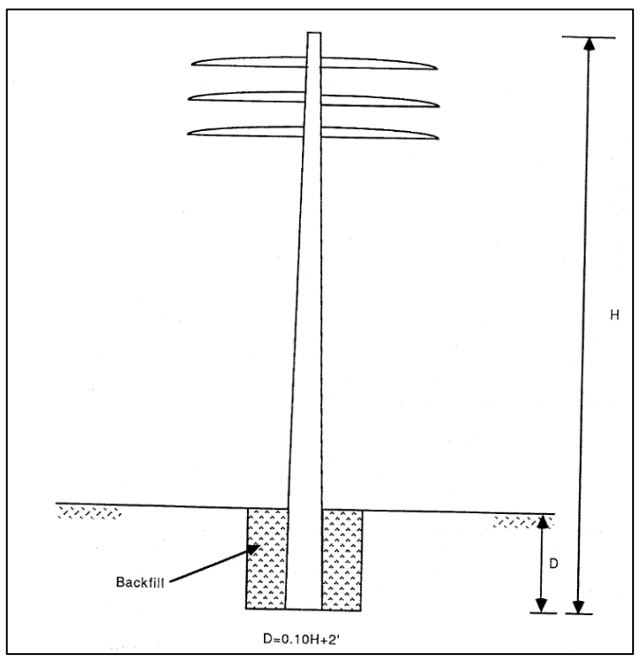
Fig 1: RUS Standard Embedment Visualization
While the traditional industry standard of 10% + Xft have been used successfully across industry for decades, this methodology can only provide a certain level of reliability. This may not meet the level of reliability utilities want for their at-risk assets. An option to increase structure reliability is to design a direct embedded foundation using site specific soil properties and structure loading. In this paper, this design process will be referred to as engineered direct embedment foundations. Engineered direct embedment foundations historically have found their uses in niche cases. One example is areas with poor soil such as wetlands or marshes where caisson foundations are difficult to construct. With changes in industry such as higher reliability requirements, bigger wires due to higher energy demand and increasingly higher liability profile, engineered direct embedment foundations are becoming more prevalent
4. MFAD Methodology
The FAD Tools is a software package that assists in the design of transmission line structure foundations. MFAD, a software included in FAD Tools, was developed from existing theoretical analytical models (e.g. Broms Method). These previous theoretical models were subsequently modified with empirical testing to obtain a semi-empirical model which provided best fit to the test results.
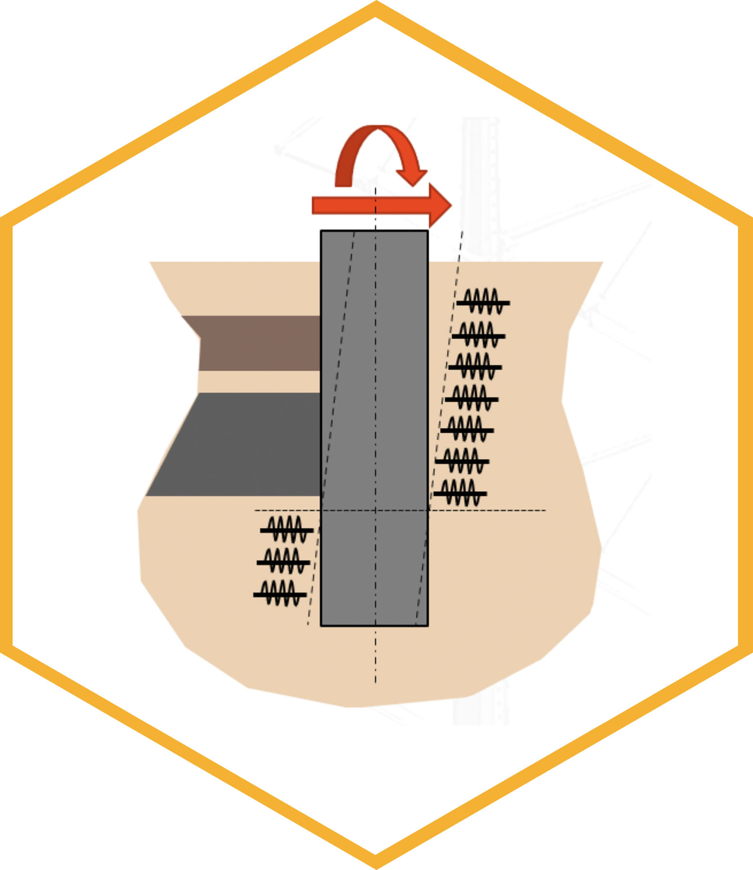
MFAD can analyze and design rigid direct embedment foundations that are subject to a lateral load with large overturning moments. For direct embedment design, a subsurface-annulus interaction analysis based on a two-spring model is used. The two spring models for direct embedment is as follows:
- Combined lateral springs are used to characterize lateral force-displacement response of the annulus and the subsurface material
- Combined rotational springs are used to characterize the moment at the foundation centerline by the shear stress at the perimeter of the pole and the perimeter of the annulus material.
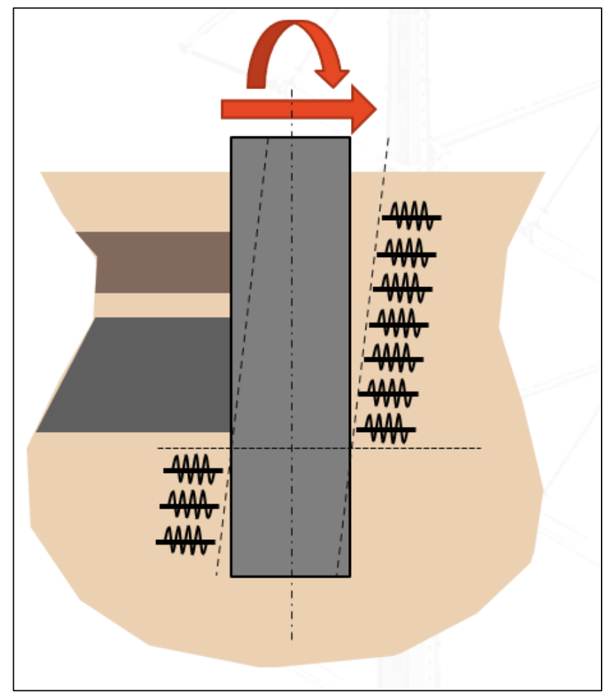
Fig 2: Visualization of Foundation Spring Model
MFAD takes the following parameters to calculate and evaluate foundations
- Foundation size – In the case of direct embedment, MFAD defines the foundation size by the outside diameter of the pole at groundline.
- Geotechnical Parameters – Design parameters that reflect the nominal subsurface conditions at structure site.
- Annulus Backfill Properties – Includes geotechnical properties of backfill and annulus thickness.
- Ground line Reactions – Loads applied to the foundation. These are compared against the strength capacity calculated in MFAD.
- Performance Criteria – Established for the design of safe and economical foundations.
4.1 Geotechnical Parameters
In nature, soil properties vary from area to area. The deformation behavior of soils can be very different depending on the soil structure. Therefore, in foundation design, detailed soil analysis is gathered by geotechnical companies at site before any foundation design is completed.
For foundations such as drilled pier, geotechnical investigation would be conducted at each structure site. Typically for direct embedment foundation design, subsurface sampling would be done every 10 or so structures. The geotechnical information used by MFAD for sub-surface modeling is as follows:
- Layer Type (Soil or rock) – Soil and rock behave differently when foundation forces are applied to them and have different MFAD parameters.
- Depth to Bottom of Soil/Rock Layers
- Groundwater Level – This parameter increases the effective unit weight of the layers below the depth to groundwater.
- Total unit Weight (pcf)
- Deformation Modulus (ksi) – This parameter is the ratio of stress in a direction to the corresponding strain in the elastic range in the same direction
- Friction Angle (degrees) – Friction angle is one of two soil strength parameters (The other being undrained shear strength). It describes the strength of granular soils such as soil with large sand content. In cemented or over consolidated unsaturated soils, both strength parameters can be used.
- Undrained Shear Strength or Rock Cohesion (ksf) – Undrained shear strength describes the strength of cohesive soil such as silty clay.
- Rock-Concrete Bond Strength (ksf) – Used along with Rock Cohesion to calculate the ultimate lateral capacity of a foundation set in rock.
Another geotechnical property that needs to be characterized is the backfill and annulus thickness. When excavating a foundation hole to set a pole in, the hole will have a diameter greater than the pole bottom. Once the pole is set, the hole will be backfilled with either concrete, slurry, or well-compacted cohesive/granular soils place in thin lifts. The strength and load-deflection response will be influenced by the dimension of the hole and the chosen backfill. Backfill parameters are as follows:
- Annulus Thickness – This characterizes the extent of the backfill. For direct embed foundations the annulus is the distance from the edge of the pole to the edge of the backfill.
- Total Unit Weight
- Deformation Modulus
- Undrained Shear Strength
- Friction Angle
- Concrete strength (If concrete is used instead of soil)
- Effective Shear Strength (If concrete is used instead of soil)
4.2 Ground Line Foundation Reactions
In recent years, typical structural design loads have been increasing. Higher energy demands call for larger conductor to carry current. Regulatory bodies in some states have directed utilities with high fire threat zones to seriously consider covered conductors to decrease forest fire probability. The effects of climate change have caused utilities to increase the wind speeds they design for. The assumptions that current standard design methodologies operate under may no longer be applicable. With respect to foundation design, the increased loads cause increased foundation reactions causing higher stress on the foundation.
Foundation reactions are the stresses which deform/deflect structure foundations. MFAD uses ground line reactions to calculate the maximum foundation stress as a function of capacity, deflection, and rotation. Foundation reactions for overhead line structures are controlled by wire loads. Other contributing loads are structure weight, ice weight, equipment weight and wind on structure. The magnitude of these loads is dependent on the structure loading criteria including probabilistic weather loads, construction loads, and maintenance loads. Other factors include wire size, wire tension and line angle.
For the purposes of this paper, we will be using the following criteria to calculate loads for our direct embedment design methodologies:
- Evaluating 69 kV single circuit tangent structures
- Conductor will be “Linnet” 336 kcmil ACSR for average loads and “Ortolan” 1033.5 kcmil ACSR for high loads
- No shield wire is being considered
- NESC standard loading
- Light District Loading (250B)
- 140 mph Extreme Wind Loading (250C)
- 0.5in Ice Thickness, 30 mph Concurrent Ice and Wind Loading (250D)
- Terminal/broken wire cases not evaluated
- Conductor was tensioned to 25% of its ultimate strength at 32 °F
- Typical MFAD methodologies uses ultimate loads. MFAD applies a resistance factor of 0.63 to the foundation capacity so that the calculated performance aligns better with empirical testing.
Once the structure loads have been calculated, the ground line reactions can be calculated.
- Moment – This can be calculated by summing lateral loads near the top of the structures and multiplying by the moment arm which is typically most of the pole. Another popular methodology for calculating moment in foundation design is to calculate the groundline moment capacity of the pole using its section modulus. This way, the foundation will share a moment capacity with the pole. For the purposes of this paper, we are calculating moments from applied loads.
- Shear – Like moment, shear can be calculated based on structure loads or be designed based on pole capacity. Calculating shear either way gets to be more complex as you add wires at different levels. This will change the length from ground level to the centroid of applied loading on the pole. For the purposes of this paper, we are calculating shear from applied loads.
- Axial – The axial load is the sum of weight of the structure, equipment, any ice and the wire weight.
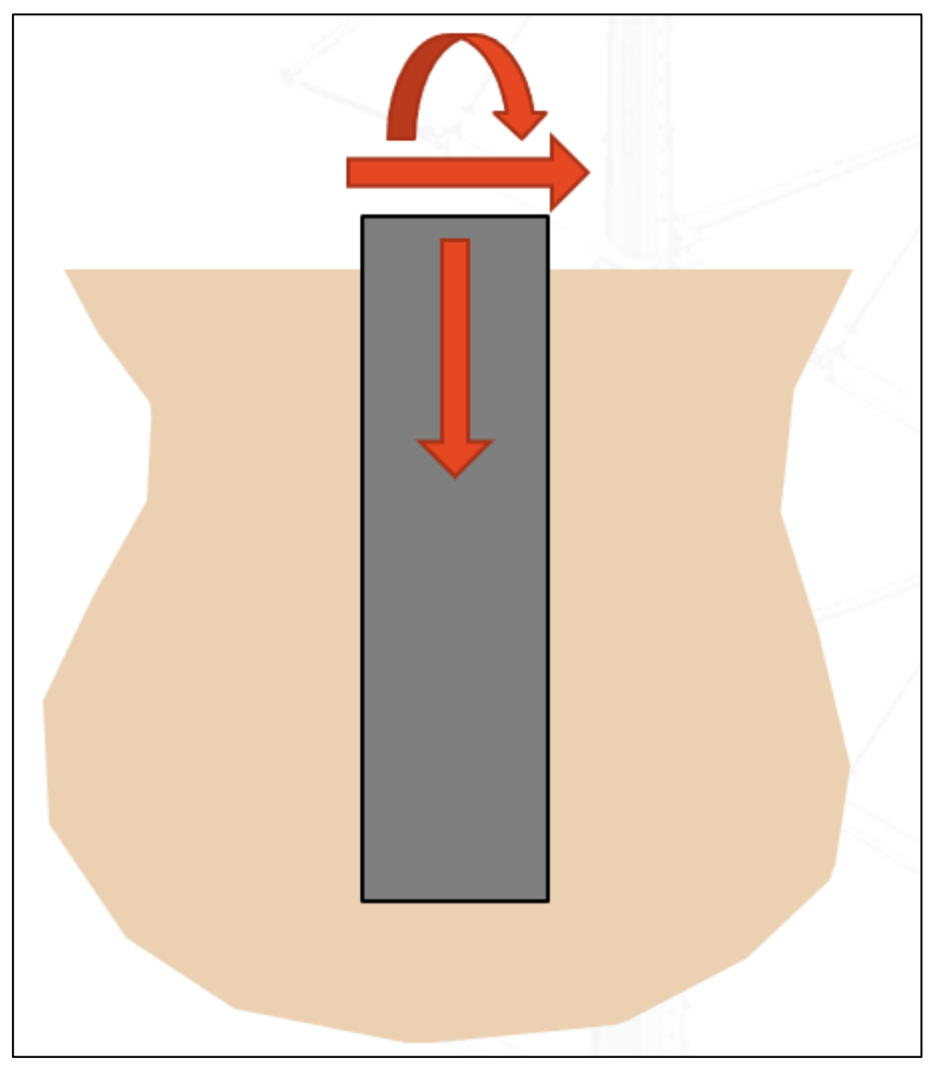
Fig 3: Visualization of Moment, Shear and Axial Reactions on Foundation
The single un-guyed monopoles being analyzed in this paper act as cantilevers. Primary forces on the foundations are the consequence of loading near the top of the poles which induce high overturning moments at relatively moderate shear with low axial forces.
Structure loads and ground line reactions in this study are calculated using PLS-CADD Lite.
4.3 Performance Criteria
Along with strength capacity, performance of the foundation load-deflection response is important to limit pole tip deflection and non-recoverable foundation deflection. The performance parameters are as follows:
- Maximum allowed ground line deflection
- Maximum allowable ground line rotation
- Maximum non-recoverable ground line deflection
- Maximum non-recoverable ground line rotation
Currently, modern pole loading software can take into account a system of flexibility/deflection structure interdependencies when calculating wire loads on a structure (PLS-CADD SAPS L4). While this includes the deflection of the structure due to bending, it assumes negligible foundation deflection/rotation. To maintain accuracy in wire system modeling, foundations should be designed to limit deflection/rotation.
Standard Embedment Development
Using the methodology described in this paper, a 10% + X ft standard embedment was created for a hypothetical average situation and for a hypothetical conservative situation. These situations are simply use cases and are not necessarily indicative of standard soil or wire loads in any given service area.
Performance Criteria used for creating both standard embedment methodologies are as follows:
- Total Deflection: 1.8 in
- Total Rotation: 2 deg
- Nonrecoverable Deflection: 0.8 in
- Nonrecoverable Rotation: 1 deg
Backfill used for both methodologies is a granular soil. Properties are as follows:
- Annulus Thickness: 1 ft
- Total Unit Weight: 100 pcf
- Deformation Modulus: 0.5 ksi
- Friction Angle: 30 deg
Three cases were run for both standard embedment methodologies. Foundation reactions were calculated for a 50 ft, 60 ft & 70 ft H4 round steel pole structure.
5.1 Average Standard Embedment Methodology
When developing the average standard embedment methodology, the following geotechnical parameters were used:
| Layer Number | Layer Type | Depth to Bottom of Layer (ft) | Total Unit Weight (pcf) | Deformation Modulus (ksi) | Friction Angle (deg) | Undrained Shear Strength (ksf) | Rock Concrete Bond Strength (ksf) |
| 1 | Soil | 20 | 115 | 1 | 0 | 2 | 0 |
Soil for this case is a homogeneous cohesive soil with decent shear strength.
Loads were calculated per criteria set in Section 4.2 with Linnet ACSR. The moment and shear loads were controlled by NESC 250C. The controlling Loads are as follows:
| Structure | Shear Load (kips) | Moment (kip-ft) | Axial Load (kips) |
| 50ft-H4 | 2.87 | 102.9 | 2.7 |
| 60ft-H4 | 2.96 | 132.7 | 3.5 |
| 70ft-H4 | 3.05 | 164.0 | 3.8 |
Passing embedment depths were calculated in MFAD to the following:
| Structure | Calculated Embedment Depth (ft) |
| 50ft-H4 | 10.7 |
| 60ft-H4 | 11.2 |
| 70ft-H4 | 11.7 |
From these calculated embedment depths, 10% + 6 ft is chosen for the average standard embedment depth.
5.1 Conservative Standard Embedment Methodology
When developing the conservative standard embedment methodology, the following geotechnical Parameters were used:
| Layer Number | Layer Type | Depth to Bottom of Layer (ft) | Total Unit Weight (pcf) | Deformation Modulus (ksi) | Friction Angle (deg) | Undrained Shear Strength (ksf) | Rock Concrete Bond Strength (ksf) |
| 1 | Soil | 1 | 100 | 0.5 | 15 | 0 | 0 |
| 2 | Soil | 5 | 100 | 0.5 | 20 | 0 | 0 |
| 3 | Soil | 10 | 110 | 2 | 25 | 0 | 0 |
| 4 | Soil | 20 | 110 | 4 | 30 | 0 | 0 |
Soil for this case is a granular soil with poor strength on the top layers.
Loads were calculated per criteria set in Section 4.2 with Ortolan ACSR. The moment and shear loads were controlled by NESC 250C. The controlling Loads are as follows:
| Structure | Shear Load (kips) | Moment (kip-ft) | Axial Load (kips) |
| 50ft-H4 | 4.83 | 174.3 | 3.95 |
| 60ft-H4 | 4.98 | 224.5 | 4.75 |
| 70ft-H4 | 5.13 | 277.2 | 5.05 |
Passing embedment depths were calculated in MFAD to the following:
| Structure | Calculated Embedment Depth (ft) |
| 50ft-H4 | 14.4 |
| 60ft-H4 | 15.4 |
| 70ft-H4 | 16.2 |
From these calculated embedment depths, 10% + 10 ft is chosen for the conservative standard embedment depth.
6. Engineered Direct Embedment vs Standard Embedment
To compare these difference methodologies, three use cases were developed. They use the same parameters as in Section 5 other than the parameters mentioned below:
6.1 Case 1
| Layer Number | Layer Type | Depth to Bottom of Layer (ft) | Total Unit Weight (pcf) | Deformation Modulus (ksi) | Friction Angle (deg) | Undrained Shear Strength (ksf) | Rock Concrete Bond Strength (ksf) |
| 1 | Soil | 5 | 120 | 0.5 | 0 | 0.25 | 0 |
| 2 | Soil | 20 | 120 | 1 | 0 | 0.75 | 0 |
Case 1 is a 65ft H4 Steel pole embedded in a cohesive soil with low shear strength.
6.2 Case 2
| Layer Number | Layer Type | Depth to Bottom of Layer (ft) | Total Unit Weight (pcf) | Deformation Modulus (ksi) | Friction Angle (deg) | Undrained Shear Strength (ksf) | Rock Concrete Bond Strength (ksf) |
| 1 | Soil | 5 | 30 | 0.1 | 28 | 0 | 0 |
| 2 | Soil | 18.5 | 131 | 3.02 | 0 | 4 | 0 |
| 3 | Soil | 30 | 128 | 3.75 | 0 | 4 | 0 |
6.3 Case 3
| Layer Number | Layer Type | Depth to Bottom of Layer (ft) | Total Unit Weight (pcf) | Deformation Modulus (ksi) | Friction Angle (deg) | Undrained Shear Strength (ksf) | Rock Concrete Bond Strength (ksf) |
| 1 | Soil | 3 | 110 | 0.2 | 20 | 0 | 0 |
| 2 | Soil | 10 | 115 | 1 | 32 | 0 | 0 |
| 3 | Rock | 20 | 140 | 13 | 0 | 5 | 20 |
Case 3 is a 75ft H4 Steel Pole embedded in a granular top layer of soil with a deeper rock layer.
6.4 Results
The calculated embedment depths are as follows:
| Case | Calculated Embedment – Linnet Loads (ft) | Calculated Embedment – Ortolan Loads (ft) | Embedment Depth Average Methodology (ft) | Embedment Depth -Conservative Methodology (ft) |
| Case 1 | 13.5 | 16.5 | 12.5 | 16.5 |
| Case 2 | 11.9 | 14.0 | 14.0 | 18.0 |
| Case 3 | 12.0 | 14.6 | 13.5 | 17.5 |
In Case 1, the soils are worse than the soils used to calculate the average standard embedment. As such, the embedment requirement is more for calculated linnet loads are higher than average standard embedment of 10% + 6 ft.
In Case 2, the calculated embedment depth with linnet loads is lower than the average standard embedment. This is for two reasons. One, the soils for this case are relatively good. Two, this structure is much taller than the structure that controlled the embedment depth (50 ft H4) for the average standard embedment calculation. As shown in the standard methodology development, the shorter poles controlled the 10% + X ft.
In Case 3, again the calculated embedment depth with linnet loads is lower than the average standard embedment. This is because the foundation takes advantage of the rock layer. Another advantage here is that the calculated embedment doesn’t require too much rock excavation.
7. Methodology Evaluation
When evaluating these different methodologies, this paper looks at the overall reliability the methodology offers, the amount of engineering effort required by the methodology and the amount of construction effort by the methodology. The ranking (1 being the best performing) for each methodology is as follows:
| Criteria | Engineered Direct Embedment Design | Conservative Standard Embedment (High Loads, Bad Soil) | Average Standard Embedment (Average Loads, Average Soil) |
| Overall Reliability | 1 | 2 | 3 |
| Engineering Effort | 3 | 1 | 1 |
| Construction Effort | 2 | 3 | 1 |
When it comes to overall reliability, both the conservative standard embedment and engineered direct embedment methodologies provide high reliability. Engineered direct embedment was ranked higher due to niche cases where certain areas may have even worse soil then the ones used in the development of the standard conservative embedment.
For engineering effort, both standard methodologies were ranked 1st due to the low level of engineering effort needed to apply the methodologies. There is a ton more effort required to get geotechnical data and perform foundation analysis and design.
For construction effort, the average standard embedment was ranked 1st due to it requiring the least amount of embedment. The engineered direct embedment methodology was ranked 2nd since it will likely (although not always) have smaller embedment depths than the conservative standard embedment depth.
9. Observations and Conclusions
The transmission line industry is changing. With higher energy demands, an increasing liability profile and ever-increasing adverse conditions, utilities are investigating processes which deal with these issues in a cost-effective manner. By focusing on at-risk assets, utilities are able increase overall system reliability by addressing the assets that are most likely to fail. With this increasingly higher focus of asrisk assets, one avenue utilities have been exploring to increase the reliability of these assets is to reevaluate how to design/engineer direct embedment foundation of these assets.
Historically, many utilities have been fine with the reliability offered by standard embedment methodologies. Currently, because of the above-mentioned changes, the use of engineered direct embedment foundations is growing more prominent.
From the findings of this paper, there are many methodologies with pluses or minuses. Engineered direct embedment foundations offer more reliability at a steeper cost. One final option that can be presented is a hybrid approaches to foundations where different foundation design methodologies may be used based on the situation. In doing so, utilities can both increase their reliability of their system while keeping cost down.
10. References
1 Electric Power Research Institute, FAD Tools, FAD 5.1 User’s Guide, USA, 2005
2 Design of Direct Embedment Foundations for Poles Under Moment Loads in Granular Soils, Prasad Yenumula, Asim Haldar, Chari T.R
3 Design of Steel Transmission Pole Structures, ASCE 48-19
4 National Electric Safety Code, NESC 2017
5 Design manual for High voltage transmission lines, RUS Bulletin 1724E-200
6 Study of Electric Transmission Line Deep Foundation Design, P.M. Kandaris and S. Davidow
7 Deep Dive into Transmission Line Structure Selection, Scott Dodds, S. Chitre