
1. Abstract
Geometry of a transmission line structure plays a vital role in the overall design of the transmission line. Improper geometric design due to excessive phase spacing in a transmission line structure may result in uneconomical transmission line designs driving up the cost of the overall project. On the other hand, inadequate phase spacing in transmission line structures will result in phase-to-phase flashovers which could prove catastrophic. With increasing energy demand, there is a need for utilities to optimize the structural geometry based on the different critical parameters. For instance, certain utilities would have energized climbing requirements on their higher voltage transmission line structures, which will require calculating the minimum approach distance (MAD) along with the electrical clearance envelope assessment. Determination of an appropriate shielding angle and considering clearances related to galloping will play a role in shaping the transmission line structure geometry.
In this paper, 2-ckt 230kV transmission line structures were considered – lattice tower and steel monopole, in a vertical tangent configuration. For both structure types, the most compact base geometry was formulated as a datum, using the minimum clearance requirements per National Electric Safety Code (NESC), Rule 235. Different parameters such as energized climbing/working requirement, shielding angle, galloping clearances, etc. were independently investigated to study their effect on the structures’ geometry. Furthermore, I-string and V-string insulator assemblies were considered for these structure types to evaluate the effect of insulator swing under different weather conditions on the geometric design. The primary intent of this paper was to demonstrate various factors affecting the geometry of transmission line structures and to provide recommendations to optimize the same.
2. Background
Design of a transmission line structure is of paramount importance since it affects the usability of the structure under current and future transmission line requirements. In addition to the structural loading requirements, in terms of the different load cases, deflections, design spans and conductor tensions, transmission line structures need to be designed for electrical requirements, all of which affect the geometry of the structure. A transmission line structure designed for limited parameters, when installed, will have limited functionality and is often not capable of future loading and clearance requirements. For example, a structure that has not been designed for energized climbing will require outages on its circuits for any maintenance work. In some instances, project engineers must come up with reactive remediation measures to be able to meet future demands and not have to outright replace the structure. Such a structure may have been cost effective in terms of its material and installation cost, but a transmission line with such structures installed will have increased maintenance and outage requirements, in addition to safety related concerns.
In this paper, firstly, various parameters affecting the structure geometry are considered. For each parameter, we have discussed the different ways utilities can design the transmission line structures. Altering structure geometry to consider the effect of these parameters is a common option that utilities may consider; however, the extent to which the structure geometry will need to be altered, which will have an impact on the overall cost of the structure, depends on the sensitivity of the structure geometry to each parameter. To analyze this sensitivity, a problem statement is considered, where a 2-ckt 230kV vertical configuration steel pole and tower’s geometry is independently designed for the three parameters considered – galloping, lightning protection and energized climbing requirements. The effect of insulator assembly on a structure’s geometry is also investigated by comparing I-string and V-string assemblies.
The primary objective of this paper is to bring to the readers’ attention the various parameters that can be taken into consideration while designing a new transmission line structure. In order to make the transmission line infrastructure more robust and usable, the transmission line structures’ geometries will need to be able to accommodate for those requirements. Readers can then assess the trade-offs for making geometric alterations to transmission line structures versus accounting for other alternatives and hence estimate the cost-effectiveness.
3. Parameters affecting Structure Geometry
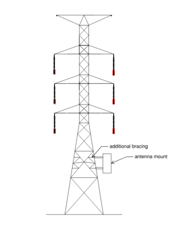
Primarily, a transmission line structure design depends on the design loading and clearance requirements. Design loads govern the size of the structure, pole diameter and davit arm thicknesses in case of pole structures and member sizes in case of lattice towers. On the other hand, electrical clearance requirements, affect the phase-spacing, cross-arm lengths and the minimum structure height. In this paper, we have largely limited the discussion to the electrical clearance related parameters that will affect the shape of the structure. However, there are structural parameters as well, that may affect certain structures’ geometries. For example, a tangent lattice tower designed for a broken wire or stringing load will be better suited to have a square base instead of a rectangular base. Similarly, a lattice tower with an antenna mount on its leg at the center of a panel might require additional bracing to mitigate potential overstress in the tower leg due to combined axial and bending stress.
This paper limits the consideration of the following parameters,
- Galloping
- Lightning Protection
- Working and Climbing Clearances
In the next sections, each parameter is discussed in greater detail.
3.1 Galloping
Galloping is a low frequency, high amplitude wind induced vibration that can occur in both single and bundled conductors, with single or multiple loops of stationary waves within the span. The amplitudes of the stationary wave can be up to the maximum sag experienced by the conductor. In cases of distribution lines or transmission lines with slack tensions, these amplitudes can increase up to 4 times the sag. Typically, this phenomenon is caused by a relatively light wind of 30 to 35 mph blowing on an iced conductor [1] .
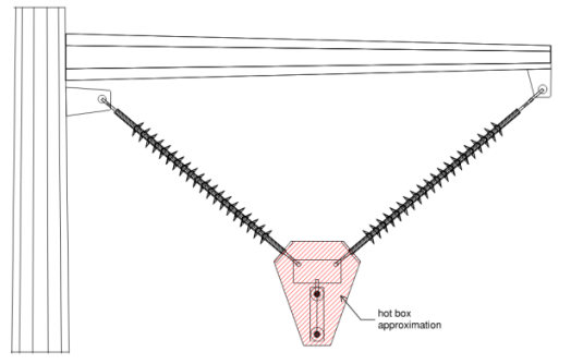
In 1930, Mr. A. E. Davison of the Hydroelectric Power Commission of Ontario, Canada presented his pioneer work on the phenomenon of galloping in transmission line conductors. Based on various observations and field data studying the motion of galloping conductors, Davison developed an empirical method for determining the conductor path which is based on the loading condition under which most cases of galloping had occurred. In this method, sag of the conductor at 32°F with 0.5” ice and a wind velocity of 30 mph is considered. The path of conductor oscillation is approximated as an elliptical loop with its major axis slightly larger than conductor sag and is tilted from the vertical in a direction opposite to the direction of the span swing by an angle equal to half of the span swing angle (SSW). This is demonstrated in the figure below. In contrast, empirical method by CIGRE B322 considers ellipses to be vertical.
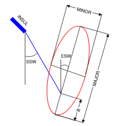
Figure 1 – Davison Model for Galloping Ellipse [4]
If there is an overlap of the galloping ellipses of different phases of the conductor or between conductor and shield wire or between conductors of different circuits, outages might occur in the transmission line also resulting in physical damage to the conductors. Hence, many utilities, that commonly experience the weather conditions described above, account for galloping clearances and sometimes include a buffer distance to establish minimum separation between galloping ellipses.
In transmission lines with larger sized conductors and longer span lengths, galloping may be observed with two or multiple loops formed within the span and the amplitude of the galloping ellipse is approximately half of the total conductor sag. There is no definite span length after which galloping will change from single loop to double loop, however, we can consider span length of 600-700 ft after which conductors are likely to gallop in two or more loops [1] . PLS-CADD utilizes Davison empirical method to model single loop galloping and Toye empirical method to model double loop galloping. Calculations for single-loop galloping ellipses are performed in PLS-CADD using the following equations, also listed in PLS-CADD version 17.20 User’s Manual [4] . All distances are input in meters (m) in the equations below.
For single loop galloping [4],
𝐸𝑆𝑊 = 𝑆𝑆𝑊/2
𝑀𝐴𝐽𝑂𝑅 = 1.25 × 𝑆𝐴𝐺 + 0.3048
𝑀𝐼𝑁𝑂𝑅 = 0.4 × 𝑀𝐴𝐽𝑂𝑅
𝐵 = 0.25 × 𝑆𝐴G
According to the REA Bulletin, weather condition of 0.5” ice, 2psf wind and 32°F must be specified for the calculation of the position of the insulator and span swing angle (SSW). To calculate SAG value, a weather condition of 0.5” ice, no wind and 32°F must be specified. With the significant consequences of galloping in mind, there are four main classes of countermeasures adopted against galloping [2]:
- Removal of ice or preventing its formation on conductors
- Implementing anti-galloping mechanisms to mitigate high amplitudes of galloping ellipses
- Increasing the line tension to reduce the sag and thereby the galloping ellipses’ amplitudes
- Provision of increased phase separation in the structure design
While methods 1 and 2 are commonly employed across various utilities in the country, it’s a good practice to account for galloping in geometric design of transmission line structures by providing increased phase spacing by adopting method 4 above. Method 3 of designing the transmission line for increased line tension is a double-edged sword since this option may introduce more problems than it would solve, such as increased stresses within the structure (strength and deflection requirements exceeding) or aeolian vibrations in the transmission line.
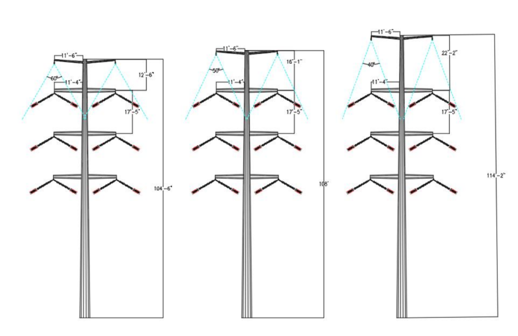
For a transmission line structure, depending on the maximum span lengths and loading conditions creating the greatest mid-span sag, galloping clearances can be determined which will allow us to determine the required phase spacing. For a structure with vertical configuration, engineers can adopt different geometry options to attain the required galloping clearance by varying the cross-arm lengths to reduce the vertical separation between cross-arms, as demonstrated below.
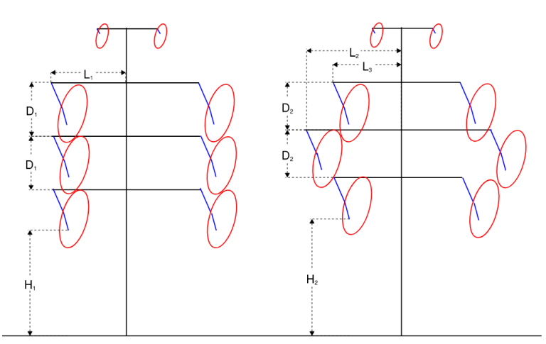
Figure 2 – Cross-arm Geometry variation for Galloping
As shown in the above figure, for the structures with same height, by varying the cross-arm lengths for the structure on the right (L2 > L1, L3 < L1), we can attain reduced cross-arm separation (D2 < D1) and thereby greater ground clearance (H2 > H1). Alternatively, if a certain clearance above ground is required, we can obtain different geometries with varying heights and/or cross-arm lengths, when checked for galloping clearances.
3.2 Lightning Protection
Fundamentally, transmission lines require lightning protection against direct strokes to the electrical conductors that can cause severe damage. The basic requirement for the design of transmission line to provide shielding against these direct strokes is by providing ground or shield wires with adequate mechanical strength, appropriately located on the structure to properly shield the conductors. Moreover, adequate clearances from line conductors to the shield wires and from the line conductors to the structures must be maintained to prevent flashover to the conductors and ensure effectiveness of the structure’s insulation.
Due to the unpredictable and probabilistic nature of lightning, different methods have been developed over the years to design for lightning protection in transmission lines. There are two methods primarily used in transmission line design,
- Empirical or classical method
o The most fundamental principle of this method is the assumption that the shield wire can intercept all the direct strokes due to lightning arriving over the subject area provided that the shield wire is encompassing over the line conductors with an angle termed as the shielding angle which is dependent on the separation and differential heights between the shield wire and conductor positions. Hence, this method of lightning protection is also referred to as the fixed angle method.
o Before 1951, a shielding angle of 30° was usually employed for transmission lines and this thumb rule produced acceptable lightning performance on existing lines up to 230kV [3] .
o For voltages greater than 230kV with taller structures, lightning performance was worse when a fixed shielding angle of 30° was considered and hence there was a requirement to develop complex models to improve the lightning performance.
- Electro-geometric design method (EGM)
o The most fundamental principle of this method is to consider shield wire’s capability of intercepting direct strokes as a function of the amplitude of the current of the stroke.
o After the poor performance of 345kV transmission line designed for a 30° shielding angle, extensive research was done to develop different EGM’s, one of which is the Rolling Sphere method.
o Rolling Sphere method was developed by Ralph H. Lee in 1977 for residential and industrial building structures’ lightning protection.
o In this method, an imaginary sphere of radius S is used and is assumed to be supported by and rolling over the shield wire forming a protective curved surface shielding any object below this surface.
While there are several special methods based on the principle of EGM which can help us improve the lightning performance of transmission lines, we are limiting the scope of the study included in this paper to the fixed angle method.
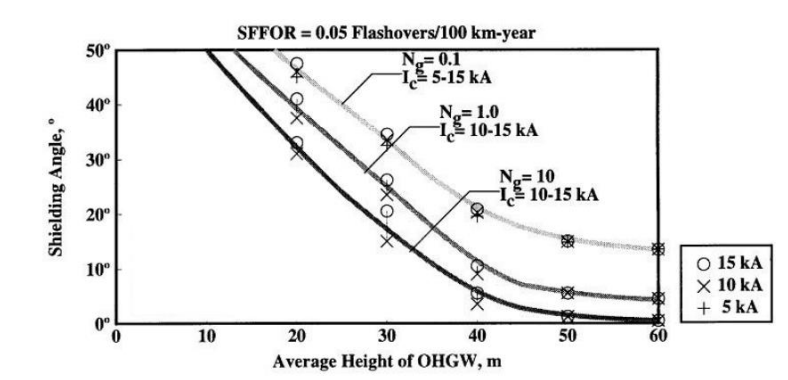
The main objective of utilizing any lightning protection method is to reduce the shielding failure rate (SFR). This can be related to the density of flashovers in a given distance per year, which is defined as Shielding Failure Flashover Rate (SFFOR). The SFFOR is a function of the line geometry and the ground flash density. For simplicity, we have considered an SFFOR of 0.05 flashovers/100 km-year which allows us to use the below curved provided in IEEE 1243-1997, to determine the appropriate shielding angle while utilizing the fixed angle method of lightning protection. In the figure below, Ng is the ground flash density or the total number of flashes in 1 km2 area in a given year. Ic is the minimum critical current required for a flashover. By observation, shielding angle required to limit the SFFOR to 0.05 flashovers/100 km-year is more dependent on the height of the shield wire position (height of the structure) than the ground flash density or the critical current.
Once a shielding angle is determined, the idea is to keep the shield wire attachments and the conductor attachments positions such that the energized portion of the conductor’s insulator assembly, usually the assembly’s corona ring or the conductor clamp, is encompassed within the shielding zone, as depicted below. Generally, the top phase conductor attachments will control the geometric design due to adequate lightning protection in a vertical or a delta configuration structure. For a structure with horizontal configuration, the outer phase conductor attachments will control the geometric design due to adequate lightning protection.

3.3 Working and Climbing Clearances
Often transmission lines and their structures require maintenance which can be done in two ways, cold line maintenance and hot line or live line maintenance. Cold line maintenance requires outages to be taken on the transmission lines that allows maintenance workers to approach the transmission line and perform necessary maintenance tasks. However, for a long period regular maintenance, utilities prefer hot line maintenance in which the transmission line stays energized and hence, there is no interruption in the power transmission.
Per Section 44, Rule 441 of the National Electric Safety Code, 2017 (NESC), supply employees shall not approach or bring any conductive object within the minimum approach distance (MAD) to exposed energized line [5]. There are exceptions to this rule when the line or the part is de-energized, or if the supply employee is using electrical protective equipment and hence is insulated from the energized line, etc. For the scope of this study, we have considered that the exceptions per NESC Rule 441 A-1 are not met, and hence, minimum approach distances (MAD) per Table 441-1 will need to be met, as shown in below table.
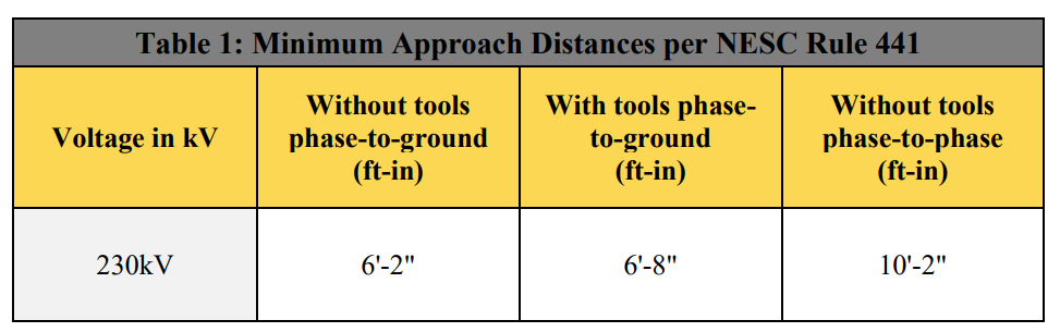
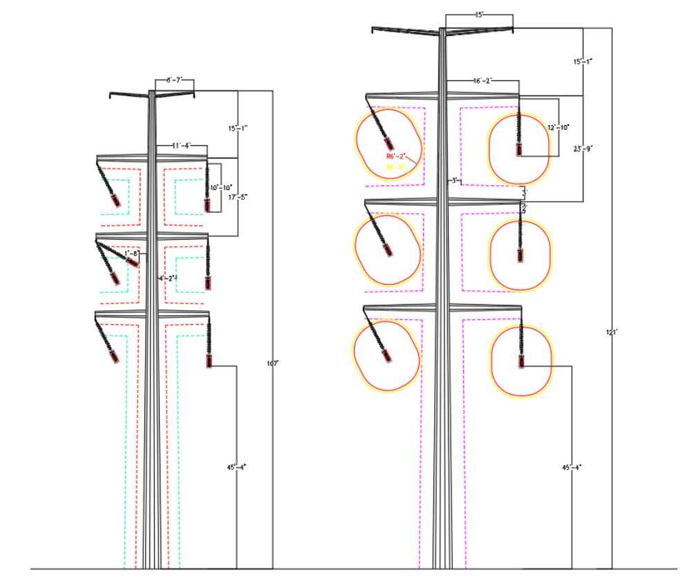
For developing clearance envelope diagrams, phase-to-ground values with and without tools are utilized such that the envelopes don’t encroach the working or climbing space of the structure.
In Figure 5, clearance envelopes are drawn around the assembly’s hot box (bundled conductors) using the MAD values from Table 1.
Working and climbing space widths can be developed around the structure based on the utility’s specification which will depend on the construction crew’s input and experience. For a transmission line structure designed for MAD clearances from energized conductors, the geometry can be further optimized by using optimum values of working and climbing clearances. For simplicity, in this study, we have considered a constant distance of 3ft around the entire structure and 2ft below the davit arms to designate its climbing and working space (demonstrated in section 5.3).
4. Problem Statement
To demonstrate the effect on structure geometry due to the parameters described above, we have considered a double circuit 230kV vertical configuration tangent (0 – 2 deg line angle) transmission line structure (steel pole and lattice tower) with 700 ft design span.
Below is some of the other criteria we have considered –
- Geometric configuration of structures o Both structures are considered with I-string insulators. Total length from the insulator attachment on structure to the edge of hot box is measured as 11’-6”. For design, the insulator swing angles are limited to approximately ±30° based on NESC 6 psf Blowout in NESC 235-6.
- Fixed shielding angle of 30° (measured from vertical) is considered.
- Bottom phase bottom sub-conductor shall have height above ground of 45’-4”.
- Wire Tensions
- 230kV conductors are of wire type 2-1590 kcmil ACSR “Falcon”. Static wire is of type 3/8” HS Steel.
- Conductor and static wire sections utilize tensions using the maximum limits per NESC 2017 Rule 261-H1, with a NESC Heavy loading district, basic wind speed of 110 mph for 250C extreme wind loading, and basic wind speed of 30 mph and ice thickness of 0.5” for 250D concurrent wind and ice loading.
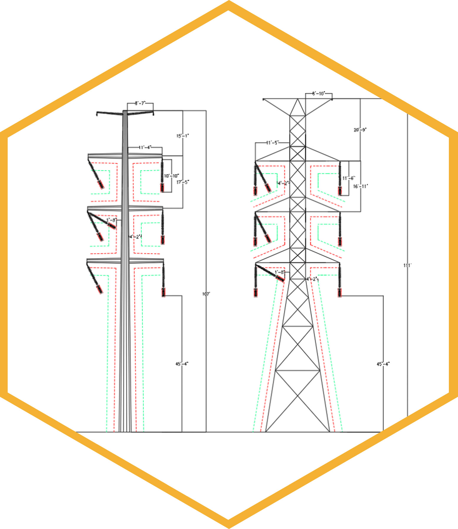
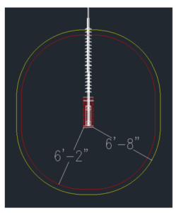
Based on the above criteria and utilizing NESC Rule 235 clearances to calculate phase-to-phase spacing, we have designed basic geometry for a 2-ckt 230kV Steel Pole and Lattice Tower, depicted below.
The phase-phase spacing and wire-to-structure clearances (dashed green line in Figure 6, 50” from structure) from Rule 235-6 is checked based on the 6 psf blowout weather condition. Insulator swing position under Extreme Wind condition (approximately measured to 60 degrees) is checked to ensure minimum flashover distance is maintained to the tower (calculated as 20” for 230kV based on RUS 1724E200). The structure geometries in Figure 6 were developed for steel pole and lattice tower structure to keep the same height of the bottom phase conductor above ground, for comparison.
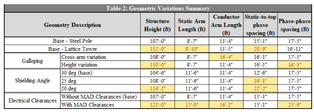
5. Geometric Variations
In the next sections, we will discuss the variations in geometry by varying different parameters one at a time and compare the resulting geometry with the base geometry (Figure 6) to better understand the sensitivity of each parameter.
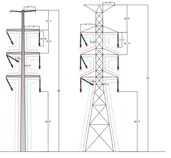
5.1 Variations due to Galloping Ellipses
As described in section 3.1, galloping ellipse dimensions largely depend on the sag of the wire. Davison model for single-loop is utilized in PLS-CADD to develop galloping ellipses for the base geometry structure. Base geometry structure has a wire tension of 35% at 60F Initial (per NESC limits), which produced a conductor sag of 13’4” and shield wire sag of 12’.
Based on these values, galloping clearances are adequately maintained for the base geometry. There is no overlap between the ellipses. No buffer distance between ellipses is considered, however, utilities may specify this additional buffer to always ensure minimum separation between the ellipses.
When the wire tensions were reduced to 25% at 60F Initial, conductor sag of 14’-6” was produced; shield wire sag remained unchanged. Galloping ellipse major and minor axes values increased and hence the geometry was revised to ensure there was no overlap between the ellipses. In Figure 7 (middle and right), geometry revision was achieved by varying the middle phase cross-arm length and pole height respectively.
5.2 Variations due to Shielding Angle
Utilizing the fixed angle lightning protection model, the shielding angular zone needs to envelope the hot box portion of the insulator assembly under all weather conditions. 250C Extreme Wind or Hurricane weather condition will produce the greatest swing angle. Hot box dimensions will need to be calculated based on the assembly hardware properties provided by the manufacturer(s). Top phase insulators swung out under hurricane wind condition will control the overall geometry of the structures, as seen in Figure 8.
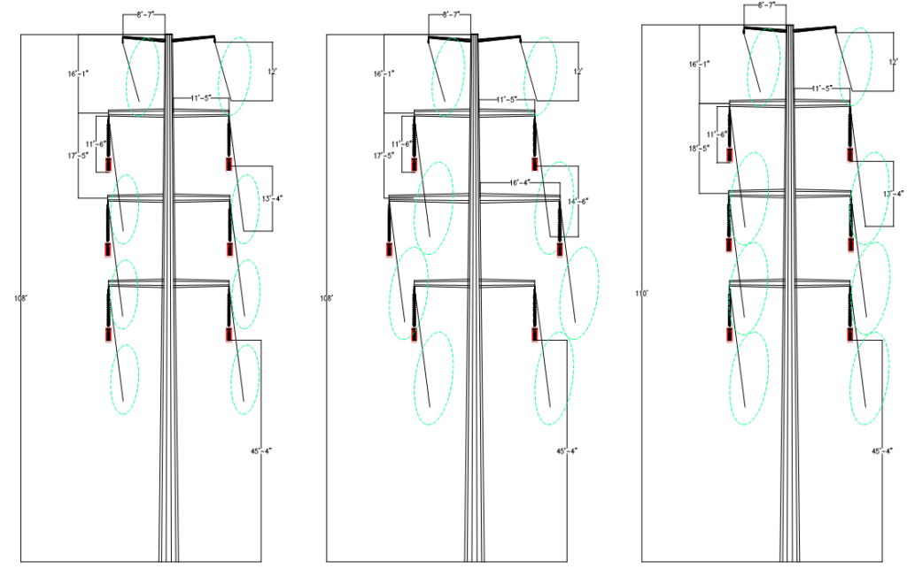
5.3 Variations due to Climbing and Working Clearances
Upon determining the minimum approach distance (MAD) values, electrical clearance envelopes can be developed as demonstrated in Figure 9. The clearance envelope that will control the geometry of the structure will be the ones that are drawing accounting for the swing of the insulator. Insulator swing angle under 250C extreme wind condition is not being considered in this study. Based on our experience, construction maintenance operations on transmission line structures, for which MAD clearances will be required, are performed under calm weather conditions. We have considered the insulator swing angle of 30° which was approximately calculated for NESC 6psf blowout condition for the problem statement criteria specified above.
6. Other parameters
Some other parameters that can influence transmission line structure’s geometry:
- Insulator assemblies
- For tangent structures, most commonly I-string, V-string or post insulator assemblies are utilized. In this study, we have considered I-string assemblies but if the structures were to be designed with V-string assemblies, geometry of the conductor arms will need to be calculated accordingly.
- For V-string assemblies, because of the limited swing of the suspension clamp in comparison to the swing of the I-string, a more compact geometry can be formulated.
- Sometimes, suspended or floating dead-end assemblies are installed on tangent structures to get additional clearance height above ground. Since the phase position is altered by installation of a floating dead-end assembly, electrical clearance and shielding angle verification for the structure’s geometry becomes vital.
- Antenna or Telecom mounts – Antenna mounting frames installed on steel poles or towers, increase structural demand. In case of towers, geometry of the panel can be modified by addition of bracing members to mitigate bending stresses.
7. Inferences
Following inferences can be drawn from the study conducted in this paper –
- In general, lattice tower structures will require greater heights and cross-arm lengths compared to steel pole structures. While accounting for wire-to-structure clearances to determine cross-arm spacing, 3-D clearances may need to be verified to ensure the adequate distances are maintained. Similarly, for some tower designs, the waist of the tower extends below the bottom cross-arm to accommodate for the inward swing of the insulator and the clearance required for the same.
- Galloping clearances can control the geometry of the structure in case the tension in the wires is low which will produce large sag values. To maintain clearances due to galloping, cross-arm lengths or the height and phase spacing of the structure will need to be adjusted in case other methods are not available.
- Shielding angle encompassing the extreme position of the insulator swing will control the geometry of the structure. As observed in Table 2, primarily, height adjustments at static level are required to get the appropriate shielding per the angle specified, which affects the overall height of the structure.
- Electrical clearances required to perform energized climbing and working is the most governing factor affecting structure geometry, of all other parameters discussed in this study. Accounting for minimum approach distance (MAD) clearance values with or without tools will affect all geometryrelated attributes as seen in Table 2.
8. References
[1] Transmission Line Design Manual, United States Department of the Interior, by Holland H. Farr
[2] CIGRE 322. B2.11.06. State of the art of Conductor Galloping
[3] IEEE 1243, Guide for Improving the Lightning Performance of Transmission Lines
[4] PLS-CADD version 17.20 User’s Manual
[5] 2017 National Electrical Safety Code (NESC)